


10
INSTALLATION
5. Place the jam nut (7) and travel index (6) over
the valve stem (11) before mounting the drive
on the valve.
6. Remove the boss nut (8) from the valve and
place the drive and yoke over the stem and
onto the boss (12). Secure the yoke with the
boss nut, finger-tight.
7. Using the drive Handwheel, lower the drive
output shaft to contact the valve stem.
Thread the valve stem into the end of the
drive output shaft. HINT: Rotate the whole
yoke /drive assembly to get the valve stem
started into the drive output shaft. Continue
lowering the drive output shaft and threading
the valve stem until the drive output shaft is
fully down on the mechanical stop.
8. Tighten the boss nut to secure the yoke and
tighten the yoke set screw (10).
9. Follow the valve seating adjustment procedure
on page 17 to complete the mounting.
Removing the Drive from a
Valve
1. Move the Group 14 output shaft up into the
drive body until the mechanical stop (3) is
tight against the lower bearing plate (1).
2. Turn off all electrical power and disconnect all
electrical wiring from the drive.
3. Loosen the valve stem jam nut (7). Loosen
the boss nut (8) on the yoke and leave it
finger tight. Loosen the yoke set screw (10).
4. Unthread the valve stem from the drive
output shaft by turning the whole yoke / drive
assembly.
Valve Installation
The Beck control drive can be mounted in
any convenient orientation. There is no preferred
operating position.
Inspect the valve body to be sure that it is
clean. Be certain that other pipelines in the area
are free from pipe scale or welding slag that
could damage the gasket surfaces.
Tighten the flange bolts and ensure that
all bolts are evenly torqued. Refer to the
gasket manufacturer’s instructions for specific
information on tightening flange bolts.
NOTE: The valve may have experienced
temperature variations in shipment. This
could result in seepage past the stem seals.
Refer to the valve manufacturer’s maintenance
instructions for packing adjustments.
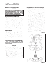
INSTALLATION—ELECTRICAL
Two conduit connections are provided in
every Beck Group 14 drive for supplying power
and signal wiring to the unit. A sealant must be
used on threaded conduit connections to keep
moisture out. Conduit should be routed from
below the drive so that condensation and other
contaminants entering the conduit cannot enter
the drive.
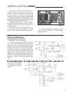
A large, clearly labeled terminal block on the
side of the drive is enclosed in a gasketed metal
enclosure. Terminals will accommodate up to 12
AWG wiring (see Figure 2, page 11).
CAUTION
Always close covers immediately after
installation or service to prevent moisture or
other foreign matter from entering the drive.
Refer to the wiring diagram furnished with
your Beck drive for proper AC power and signal
connections. It is advisable to provide normal
short circuit protection on the AC power line.
A copy of the wiring diagram is shipped with
each drive and is fastened to the inside of the
terminal block cover. If there is no wiring diagram
available, you may obtain a copy from Beck by
providing the serial number of your drive.
Your Beck drive has been supplied to match
the signal source in your control loop. If it does
not match, refer to the Input Signal Options
section of this manual, page 15, for information
on how to change the input signal.
For maximum safety, the Beck drive body
should be grounded. Normally, the electrical
conduit provides adequate ground protection.
If not, a separate ground conductor should be
connected to the drive body.
MOUNTING THE DRIVE, CONT’D.