


22
SWITCH ADJUSTMENTS
All Group 14 control drives are shipped with
end-of-travel limit switches and all auxiliary
switches factory adjusted for 100% of travel
unless otherwise specified at time of order. Limit
switches must be set inside the range of the
built-in mechanical stops to prevent stalling of the
motor.
Although the switches may be reset through
adjustment of the cam position, it is usually
advisable to change the valve travel by using the
Calibar index feature described on page 24.
Each switch should open the motor circuit
before the mechanical stop is reached. Use
the travel index on the output shaft to check the
setting. Three percent or more between the
mechanical and electrical limits is satisfactory.
To check, drive to the electrical limit using the
Handswitch, and then turn the Handwheel until
the mechanical stop is reached.
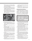
All switches are SPDT and are rated at 6 A, 120
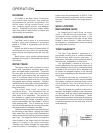
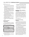
V ac. Switches are operated by cams which are
clamped on to the control shaft. Setting a switch
involves loosening the cam, moving the output
shaft to the desired position, and positioning the
cam so that it just operates the switch at that point.
In the following procedure, the use of a continuity
meter is recommended to determine when the
switch opens or closes. If such a meter is not
available, it is possible to hear the switch click as
the contacts open and close.
CAUTION
Do not attach the meter or attempt to move the
switch cams until the drive is disconnected
from the line voltage and auxiliary switches
are disconnected from external power
sources.
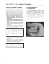
Setting Travel Limit Switches
RET and EXT
This procedure should be used if the factory
end of travel switch settings must be changed in
the field. It is advisable to operate the drive fully
each direction, using the electric Handswitch
to check switch settings before attempting to
change them. Follow these instructions if they
require adjustment.
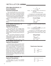
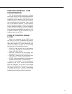
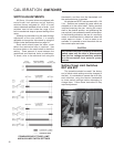
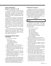
STANDARD END OF TRAVEL LIMIT
AND AUXILIARY SWITCH SETTINGS
CALIBRATION SWITCHES
FFigure 5