


11
INSTALLATION WIRING
The Group 14 drive is available with six
separate control configurations which are
provided to match the control requirements
for your system. Typical functional wiring
connections for each control option are described
in the following paragraphs and diagrams. The
wiring diagram specific to each drive is attached
to the inside of the wiring terminal cover.
Feedback connections for drives incorpor-
ating the Contactless Position Sensor (CPS-2)
for control options 6 and 8 are described on
pages 13 and 14.
A Group 14 drive can be ordered with up
to four optional auxiliary switches. Wiring
connections for these are described on page 22.
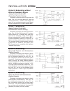
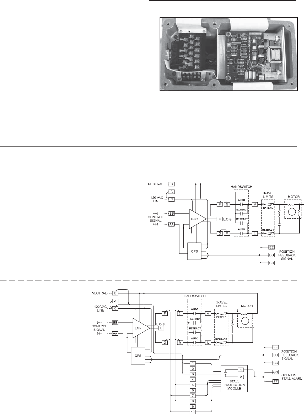
Option 8, Modulating
Analog Position Control with
Contactless Position Sensing
Customer must supply two wires to power the
drive: One 120 V ac line (terminal C), and one
neutral (terminal B). Customer must supply two
wires for the modulating analog control signal:
Connect to terminal AA (+) and to terminal BB(-).
Customer may supply two additional wires to
monitor the analog position feedback signal (see
pages 13 and 14 for connections). The drive’s
feedback circuit power supply is derived from the
120 V ac line, therefore the feedback signal must
be wired to a “4-wire” type non-powered analog
input.
To enable full Handswitch operation, connect
a 120 V ac line to terminal C (jumper between
terminals A and C).
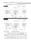
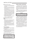
Figure 2
The wiring diagram at
right is a typical example
of an Option 8 drive with
a Stall Protection Module
installed.