


38
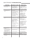
MAINTENANCE TROUBLESHOOTING
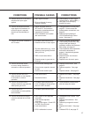
CONDITIONS
POSSIBLE CAUSES
CORRECTIONS
13. Loss of input signal feature
does not function.
14. Control drive runs to RET limit
with small change in input
signal.
15. Control drive runs to 100% and
stays.
16. Control drive travel very
nonlinear —
a. e.g., 4–19 mA change on input
causes drive to drive from 9%
to 30%; 19–20 mA change
drives 30% to 100%.
b. Response normal from zero to
mid-range; then runs to 100%.
17. L.O.S. operates at too high a
signal level.
18. CPS-2 LED goes out during
normal travel.
a. CPS-2 equipped control
drive used with ESR-4 board
calibrated for slidewire.
b. Incorrectly set potentiometer.
c. CPS-2 calibration incorrect.
a. Feedback potentiometer power
supply shorted.
b. ESR-4 circuit board failure of
2.7 V power supply (feedback
potentiometer only).
c. Wiper and low end of feedback
potentiometer reversed.
d. Open potentiometer element.
e. CPS-2 feedback out of phase
with control motor.
a. Handswitch left in RET position.
b. Potentiometer open or complete
loss of contact with wiper.
c. Loss of input signal when
FWDLOS is selected. ESR-4
LED on.
d. ESR-4 zero adjustment
incorrect.
e. ESR-4 circuit board failure.
f. CPS-2 feedback out of phase
with control motor.
g. Jumper between terminal F-N
not connected.
h. Extend limit switch failure.
a. Wiper and high end of feedback
potentiometer reversed.
b. CPS power supply failure.
a. Special requirement.
a. CPS-2 not calibrated correctly.
a. Reconnect R22 and R39
resistors and recalibrate. See
page 30.
b. Reset potentiometer. See page
26.
c. Calibrate CPS-2. See page 27.
a. Check potentiometer and wiring
for shorts.
b. Replace ESR-4 circuit board.
See page 35.
c. Check wiring on feedback
potentiometer for proper
connections.
d. Replace potentiometer.
e. Restore proper phasing of
CPS-2 feedback with control
motor. See page 27.
a. Return Handswitch to AUTO
position.
b. Check potentiometer and
replace if necessary.
c. Restore input signal to drive.
d. Readjust ESR-4 zero. See Input
Signal Calibration, page 30.
e. Replace ESR-4 circuit board.
See page 35.
f. Restore proper phasing of
CPS-2 feedback with control
motor. See page 27.
g. Connect jumper.
h. Replace limit switch. See page
34.
a. Check feedback potentiometer
for proper connections.
b. Check CPS power supply
voltage. See 21-b of this chart.
a. Change L.O.S. trip point. See
page 31.
a. Calibrate CPS-2. See page 27.