


16
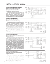
Split Range Operation
Two or three Beck drives may be operated
over their full range by a portion of the controller’s
output signal range. The most common arrange-
ment involves two drives operating on equal
halves of the input signal range. For example, if
a 4–20 mA control signal is used, the first drive
would move 100% of its stroke on a signal range
of 4–12 mA, while the second operates on the
12–20 mA portion of the signal. In this case, the
ESR-4 boards are the same as would be used
for parallel operation (13-2245-05), but calibrated
to the range required for each drive. A shunting
resistor must be added across input terminals AA
and BB on one of the Beck drives to produce a
2.0–6.0 volt span across each board for its active
portion of the range. For a 4–20 mA range three-
way split, the shunting resistor range would be
425–1,650 ohms.
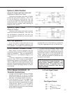
Follow the steps for calibrating the input
signal, page 30, for each drive unit, using half
span values for the input signal. Use the proper
starting point for each half-range when setting
the zero, 4 mA and 12 mA. Before setting the
zero on the second drive (12 mA), cut one lead of
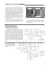
resistor R35 on the ESR-4 board. See Figure 11,
page 31, for location of R35.
In a split range configuration, connect ter-
minals E and F (L.O.S. wire) to prevent undesired
“stay-in-place” operation of the second or third
drive due to fast, downward signal changes.
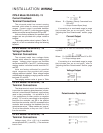
When three drives are to be operated on
equal portions of the input signal, the 4–20 mA
range would split into 4–9.33 mA, 9.33–14.67
mA, and 14.67–20 mA signals. A 487 ohm
shunting resistor (Beck P/N 13-2510-03) is
adequate. Proceed as in the case of the two-way
split, first setting span, then the zero. When
setting the ESR-4 board in the first drive, set the
zero at 4 mA. Then, on the second drive, cut
the R35 resistor on the board and set its zero at
9.33 mA. Before setting zero in the board of the
third drive, short out the R34 resistor by adding a
jumper, adjust its zero to 14.67 mA, cut resistors
R35 and R36 from the board, then remove the
jumper from R34. Check operation of all drives
by running the input signal through its complete
range. If it is necessary to recalibrate the same
board later, you may jumper resistors R35 and
R36 by connecting the R35 turrets together.
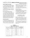
INSTALLATION WIRING OPTIONS