


18
OPERATION
HOUSING
All models of the Beck Group 14 electronic
control drive have individual, cast aluminum
compartments for the main components: The
control motor, wiring terminal board, drive
train, electronic signal receiver, and feedback
section. Gasketed covers and sealed shafts
make this product ideally suited to outdoor and
high-humidity environments.
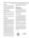
CONTROL MOTOR
The Beck control motor is a synchronous
inductor motor that operates at a constant
speed of 72 RPM in synchronism with the line
frequency.
Motors are able to reach full speed within 25
milliseconds and stop within 20 milliseconds;
actual starting and stopping times will vary with
load.
Beck motors have double grease-sealed
bearings and require no maintenance for the life
of the motor.
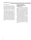
DRIVE TRAIN
The Group 14 drive train consists of a control
motor, SLM, Handwheel, reduction gears, main
gear, and power screw output shaft. The ductile
iron main gear and the bronze nut and stainless
steel power screw output shaft are common to
units of a particular range of thrust and timing.
The steel reduction gears are part of the field
changeable gear housing assembly. Different
combinations of output gear, housing assemblies,
and drive motors determine the drive’s output
thrust and timing.
The output shaft travel is limited by
mechanical stops. The mechanical stop for
the fully extended or lower limit of the output
shaft travel is not adjustable. The position of
the retracted or upward travel mechanical stop
is determined by the number of washers on the
output shaft between the Tight-Seater™ and the
lower bearing plate. This is factory-set for the
amount of travel specified at the time of the order
and is generally not changed in the field.
The amount of output shaft travel is determined
by the setting of the Calibar. Moving the Calibar
block away from the output shaft increases the
radius where the ball bearing contacts the sector
gear lever. The longer the radius the longer the
vertical stroke of the output shaft for the same
amount of rotation of the control end shaft.
Therefore, the Calibar changes the output shaft
travel but makes it unnecessary to change the
switch cams, film potentiometer, or CPS-2. Field
Calibar adjustment is generally used to shorten
the travel. Consult the factory if a longer stroke is
required.
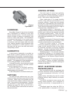
SELF-LOCKING
MECHANISM (SLM)
An integral part of every Group 14 control
motor is the self-locking mechanism. This
mechanical device couples the motor to the
gear train and transmits full motor torque when
rotated in either direction. When the motor is
de-energized, it instantaneously locks and holds
the output shaft in position.
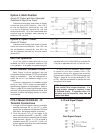
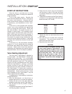
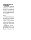
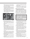
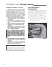
TIGHT-SEATER™
The Beck Tight-Seater™ assembly is a
pre-loaded coupling that is installed between
the drive output shaft and the valve stem. It
produces a controlled positive pressure against
the valve seat, independent of drive thrust.
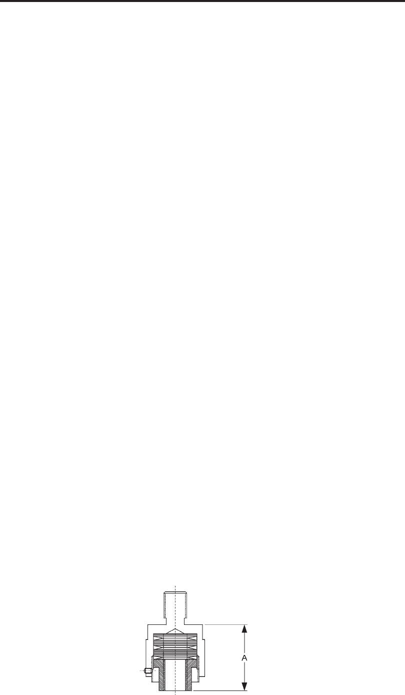
The Tight-Seater™ consists of four parts: A
housing attached to the output shaft, linear thrust
discs contained in the housing, a flanged coupling
attached to the valve stem, and a threaded ring
to contain the flanged coupling in the housing
and to allow adjustment of the pre-load on linear
thrust discs.
The factory pre-load, by a threaded ring,
ensures that no relative motion occurs between
the flanged coupling and housing during normal
valve operation until the pre-load thrust is
exceeded in the seated plug position of the
valve.
When the seated plug position of the valve is
reached, the flanged coupling on the valve stem
is stationary, and the output shaft exceeds the
pre-load pressure of the Tight-Seater™. When
the pre-loaded pressure is exceeded, the housing
will compress the linear thrust discs, maintaining
a controlled pressure on the valve seat, with the
shaft stationary.
Figure 3
Tight-Seater™
Cross-Section