


36
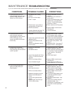
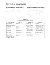
CONDITIONS
POSSIBLE CAUSES
CORRECTIONS
If your unit contains a Stall Protection Module (SPM) refer to publication 80-0017-03, page 7, “Troubleshooting”.
1. Control drive will not run in
either direction with input signal
applied to ESR-4 Board. No
lamps lit on ESR-4 board.
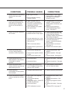
2. Control drive will not run in
either direction with input
signal applied to ESR-4 board.
CPS-2 LED light out and
jumper removed from monitor
board relay.
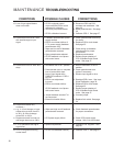
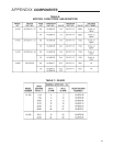
3. Control drive runs in one
direction only in AUTO, and
both directions with Handswitch
in RET and EXT.
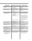
4. Loss of ESR-4 signal lamp
lights (red LED) with input
signal applied.
a. Handswitch left in wrong
position.
b. No 120 V ac line supply.
c. Fuse F-1 open.
d. External auto / man switch in
wrong position (Position-AII).
e. ESR-4 board failure.
f. Jumpers between terminals F-N
and D-M are not connected.
a. No power.
b. Control drive positioned beyond
calibrated limits.
c. CPS-2 rotor position not set
properly.
d. CPS-2 not calibrated correctly.
e. CPS-2 failure.
a. ESR-4 zero adjustment
incorrect.
b. Handswitch failure.
c. Loss of input signal with “Drive
to Zero” or “Drive to full travel”
selected.
d. ESR-4 circuit board failure.
e. Loss of feedback signal.
a. ESR-4 zero adjustment
incorrect.
b. Input signal reversed.
c. ESR-4 circuit board failure.
d. Slidewire equipped drive with
ESR-4 board calibrated for
CPS-2.
e. Incorrect film potentiometer
setting.
f. Control signal wired through
CPS-2 monitor relay.
a. Return Handswitch to
AUTO
position.
b. Check fuses and switches in
power panel.
c. Check for possible shorts, then
replace fuse. Use only Beck
part no. 13-2230-03 for proper
protection of triacs.
d. Return switch to AUTO position.
e. Replace ESR-4 circuit board.
See page 35.
f. Connect jumpers.
a. Check power source. Check
CPS-2 power supply voltage.
Check CPS-2 power transformer.
b. Position drive with Handwheel
and check limit switch settings.
c. Set CPS-2 rotor position. See
page 35.
d. Calibrate CPS-2. See page 27.
e. Replace CPS-2. See page 35.
a. Readjust ESR-4 zero. See Input
Signal Calibration, page 30.
b. Check continuity from terminal N
to V and M to U with Handswitch
in auto position. See wiring
diagram.
c. Check input signal.
d. Replace ESR-4 circuit board.
See page 35.
e. Check signal from CPS-2 or
potentiometer at TP3 on ESR-4.
a. Readjust ESR-4 zero. See Input
Signal Calibration, page 30.
b. Check polarity of input signal.
Terminal AA (+), Terminal BB (-).
c. Replace ESR-4 circuit board.
See page 35.
d. Cut R22 and R39 resistors and
recalibrate the ESR-4 board.
See page 30.
e. Reset film potentiometer. See
page 26.
f. Control drive position beyond
calibrated range. Use
Handswitch or Handwheel to put
drive within normal operating
range.
MAINTENANCE TROUBLESHOOTING