


24
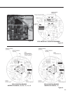
CALIBRATION STROKE CHANGE
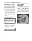
STROKE CHANGE—CALIBAR
Adjustment of the total drive stroke within the
factory-set travel range is easily accomplished
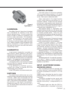
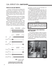
by the use of the Beck Calibar, Figure 7. The
switches and feedback device are simultaneously
adjusted to maintain full input span when the
Calibar setting is changed. For stroke lengths
longer than the factory-set travel limits, consult
the factory. Adjust the drive stroke as follows:
1. Remove the top cover. The protective O-ring
seal will remain in the rim of the top cover
when removed.
2. The Calibar index is graduated directly in
inches, which corresponds to the drive travel
span.
3. Loosen the two locking screws on the Calibar
block with an 1/8" hex wrench (See Figure 7,
this page).
4. Slide the Calibar block, aligning the notch
with the desired travel span on the Calibar
index. Tighten the set screws.
NOTE: If increasing the travel span within
the factory-set travel range, a portion of
the upper mechanical stop will have to be
removed and the Calibar index plate notch
should be enlarged to accommodate the
adjustment of the Calibar block to the new
stroke.
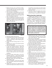
5. Use the Handswitch to operate the drive and
check the stroke on the travel index of the
valve yoke.
6. Replace the top cover after making
adjustments. Tighten the top cover just
enough to compress the O-ring seal.
NOTE: The limit switches and feedback
device are adjusted automatically when the
Calibar setting is changed. Do not adjust the
limit switch cams to change the drive stroke.
STROKE AND SPAN
ADJUSTMENTS
The Calibar adjustment is designed to allow
field changes of the total drive stroke with the
same maximum input signal applied (e.g., a
change from 1 1/2" stroke with 20 mA input signal
to a 1“ stroke with 20 mA input signal).
The span adjustment on the ESR-4 board is
used to maintain the drive stroke when a change
in input signal (or span) is required (e.g., a
change from 3/4" stroke with a 20 mA maximum
input signal applied to 3/4" stroke with an 18 mA
maximum input signal applied).
Figure 7