


30
INPUT SIGNAL CALIBRATION
All Group 14 drives equipped for milliamp
or dc analog modulating applications include
a fourth generation Electronic Signal Receiver
(ESR-4). The ESR-4 board consists of a voltage
regulator, a signal amplifier, an error amplifier,
and three solid state output switches.
The ESR-4 board controls the position of
the Beck drive according to the input signal it
receives. A feedback signal is delivered to the
board from either a potentiometer or the CPS-2,
which is then compared with the input signal.
The error signal is amplified and used to actuate
either of two switches to retract or extend the
output shaft until the signals balance and the
error is zero.
The third output switch is energized when
the signal falls below a given setting. This
L.O.S. can be used to drive the output shaft to a
predetermined position. See section on L.O.S.,
page 28, for further details.
NOTE: The input signal is calibrated relative
to the output (feedback) signal. Therefore,
the shaft travel limit switches must be
properly adjusted and the feedback signal
calibrated before the input signal can be
calibrated.
Checking Calibration
Using the input control signal, drive the
output shaft through its complete range. Check
the position feedback signal to confirm that a
10% input signal delivers a 10% position, a 50%
signal delivers a 50% position, and a 90% signal
delivers a 90% position. If the feedback signals
do not correspond to the appropriate input
signals, then the ESR-4 must be calibrated. The
tolerance on factory calibration is ±0.5% of span.
CAUTION
The signal circuit on ESR-4 units is not
grounded. If grounding is required, connect
terminal BB in the terminal compartment
to ground, either on the drive body or
externally.
Calibration Tips
The input signal can be varied by the
automatic controller, but if that is impractical, a
test box may be used. Connect the test box to
positive terminal AA and negative terminal BB of
the terminal block in place of the controller input.
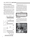
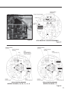
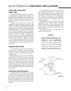
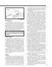
Span and zero adjustments are located near
the edge of the ESR-4 board (see Figure 11,
page 31). Monitor the FWD and REV lamps to
make adjustments. When the drive is balanced
or in L.O.S. mode, both lamps are on. When
the output shaft is moving, the lamp designating
its direction of travel goes out. When the drive
reaches its end of travel before balance is
achieved, the lamp will stay out. Trim the adjust-
ment so that the drive just reaches the limit switch
and the motor does not run. Clockwise rotation
of either span or zero adjustment causes the
output shaft to drive toward the zero (minimum
input signal) position.
Calibration Procedure
The following procedure should be followed
to calibrate the ESR-4 board.
Tools required:
3/32" Screwdriver
1/2" Combination Wrench
1. Open the Electronic Signal Receiver and
Terminal compartment cover (1/2" bolt
heads).
2. Short input terminals AA and BB.
3. Turn electric Handswitch to AUTO position.
4. Short out resistor R35 temporarily with a clip
lead (see Figure 11, page 31, for location of
R35). NOTE: Drive will retract.
5. Using a 3/32" screwdriver, turn the zero
adjustment potentiometer clockwise to its
maximum position. Drive will run to zero
position travel limit (full extension).
6. Remove short on input terminals and, using
controller or test box, apply an input signal
equal to span (e.g. 16 mA for 4–20 mA span)
NOTE: Drive may run.
7. Using a 3/32" screwdriver, turn the span
adjustment potentiometer clockwise until
drive runs, then counterclockwise until drive
just reaches 100% position.
8. Remove the clip lead on resistor R35 so
that it is not shorted. Apply 100%, full range
position signal (e.g. 20 mA).
9. Turn zero potentiometer counterclockwise to
position the drive at the 100% position (may
require 10–15 turns).
10. Drive the output shaft to the minimum input
signal position (e.g. 4 mA). If necessary,
turn the zero potentiometer to trim the zero
position.
11. Return the drive to the 100% position. If
necessary, position the drive using the span
potentiometer.
CALIBRATION INPUT SIGNAL