


28
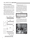
CALIBRATION FEEDBACK SIGNAL
2. Remove jumper from terminals CC to DD and
replace with a 3.01K ohm resistor (see Table
11, page 46). This shifts the range to 4–20 V
dc.
3. Using a voltmeter at the appropriate output
terminals, adjust the Zero Potentiometer with
the drive at minimum input signal position so
that output reads 0 V dc. This changes the
range to 0–16 V dc.
FEEDBACK SIGNAL MONITOR /
ISOLATOR
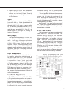
CPS-2 models 20-3400-12, -13, -14, and -15
are provided with a Monitor / lsolator board which
delivers an isolated position feedback signal to
the Electronic Signal Receiver (ESR-4). The
Monitor function monitors the CPS-2 position
signal and compares it to established limits. If
the output is outside normal signal conditions,
the monitor relay contact opens. This relay may
be used for either a remote signal indication
or activation of Loss of Signal operation of the
drive.
No adjustments should be made on the
Monitor / Isolator board.
Signal Monitor Sensing
Operation
A red LED indicator and an SPST relay are
mounted on the Monitor / lsolator board to indicate
that power is on and that the CPS-2 output signal
is within normal range. Normal operating range
is -1% to +101% (contacts closed) and -4% to
+104% (contacts open).
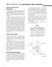
The SPST relay is rated for 0.1 amp resistive
at 100 V dc and can be used for remote monitoring
of the drive’s power or to signal a system failure.
Loss of Signal Operation
Group 14 drives equipped with Electronic
Signal Receivers (ESR-4) are configured so that
the input control signal is connected through the
relay on the monitor board of the CPS-2. The
Loss of Signal (L.O.S.) function of the ESR-4 may
therefore be activated when the CPS-2 signals
are outside the normal range (see above). To
have an out-of-range CPS-2 signal trigger the
L.O.S. mode, remove the jumper across the
relay contacts on the monitor board. See the
schematic on page 48 for jumper location. For
details on L.O.S. function, review the following
section on Input Signal Calibration.
ends. CCW movement of the Potentiometer
decreases the span equally at both ends
(see Figure 9, page 29, for location of Span
Potentiometer).
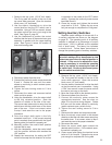
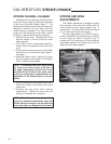
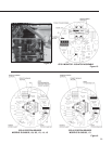
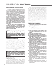
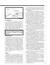
8. Loosen the rotor clamp and reset its position
(use the thickness gauge; see Figure 8, page
29) to achieve the desired value of maximum
output signal. For example, 20 mA. NOTE:
Rotor adjustment moves the entire span up or
down. Also observe the meter as you rotate
the rotor to ensure that the signal is changing
in the proper direction.
9. Tighten the rotor clamp to 5 Ib-in torque.
10. Move the output shaft to the fully extended
and fully retracted positions and check the
output signal for desired span. If not correct,
repeat the procedure from step 5.
11. Remove the meter and resistor, reconnect
feedback wires, and replace covers.
12. Torque the terminal cover bolts to 10 Ib-ft.
Tighten the top cover bolt just enough to
compress the O-ring seal.
13. Return electric Handswitch to AUTO position
and process controller to automatic mode.
14. On Model 14-108, recalibrate the ESR-4
board.
Adjusting the Zero
Potentiometer
The Zero Potentiometer is provided on
CPS-2 models 20-3400-03 and -13 to change
from a suppressed zero to a zero-based range
(e.g. from 1– 5 V dc to 0–16 V dc). The zero is
adjustable from - 5% to +30% of span.
NOTE: Do not adjust the zero potentiometer
to shift calibration. Adjust the rotor position
only to shift calibration.
CAUTION
The zero is factory sealed on all CPS-2
units except 20-3400-03 and -13. Do not
attempt to adjust the zero on other models as
misadjustment of feedback signal and monitor
/ isolator functions of the ESR-4 will result.
The following example is given to illustrate
how the zero is adjusted to effect a range change
from 1–5 V dc to 0–16 V dc.
1. Install the 1–5 V dc unit as a 1–5 V dc range.
Do not make any adjustments other than
setting the rotor position.
CPS-2 CALIBRATION, CONT’D.