


35
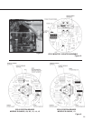
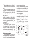
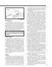
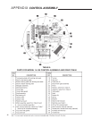
Figure 13
Handswitch
To replace the Handswitch, remove the
terminal cover, ESR-4 board and ESR-4 bracket.
Clip the five wires from the old Handswitch.
Remove the knob and the nut under the knob to
remove the switch. Install the new Handswitch as
shown in Figure 13, above. Splice the wires color
for color. Replace the ESR-4 bracket, board and
the terminal cover. Torque bolts to 10 lb-ft.
NOTE: The AUTO position on the Handswitch
knob must be straight up when the switch is
fully clockwise. Handswitch part number
20-3300-27.
ESR-4 Board
Field service of the ESR-4 board is not
recommended. The factory maintains a stock
of replacement boards for immediate shipment.
To replace the ESR-4 board, open the terminal
compartment cover (1/2" bolt heads). Loosen
the four captive screws holding the board to its
mounting pads. Note the “L” shape mounting
bracket on the end of the board; to remove, pull the
mounting bracket away from its mating surface.
To install an ESR-4 board, lightly press the
board connector into its receptacle until the
mounting bracket is flush with its mounting
surface. Tighten the four captive screws and
close the compartment cover. Torque the cover
bolts to 10 Ib-ft.
CPS-2
Field repair of the CPS-2 assembly is not
recommended. The factory maintains a stock of
replacement assemblies for immediate shipment.
If it is necessary to replace the CPS-2, replace
both the rotor and stator / circuit board assembly.
When returning the CPS-2 to the factory
for service, please include the rotor and stator
/ circuit board assembly. Do not separate the
stator or circuit boards from their mounting plate.
It is recommended that the rotor be held inside
the stator with rubber bands and the hex studs
be reattached to the mounting plate for protection
during shipment.
To remove the CPS-2, remove the top cover
and run the drive to the 0% position (100% for
Model 20-3400-04 & -14 if used for 0–15 V dc
signal). Note direction of shaft rotation. Turn the
Handswitch to STOP and turn off all AC power to
the drive. Disconnect the wires from transformer
and spring clamp terminals. See Figure 10, page
29. Note wire colors and locations. Pull wires
through the mounting plate hole. Loosen the
rotor coupling and remove the three hex stud nuts
supporting the CPS-2 assembly. Support the
inboard hex stud when removing nuts. Remove the
CPS-2 stator / circuit board assembly and rotor.
To install the CPS-2, slide the rotor onto
the control shaft (clamp end toward the limit
switches). Leave the clamp loose. Assemble
CPS-2 over the rotor and mounting studs,
transformer out and at approximately 4 o’clock.
Secure assembly with three hex nuts. Torque to
60 Ib-in. Reconnect wires.
To set CPS-2 rotor position, open the terminal
cover (1/2" bolt heads) and connect a mA / V dc
multimeter to the feedback terminals. See wiring
diagram supplied with drive or Table 11, page 46,
for correct terminals. Run drive to 0% position
(100% for model 20-3400-04 & -14 if used for
0–15 V dc signal). Note direction of control shaft
rotation. Put Handswitch in STOP. Insert .031“
thickness gauge between rotor clamp and stator.
See Figure 8, page 29. Position the rotor so that
the slot in the rotor is aligned with the wire holes
and transformer on CPS-2 board.
Set 0% rotor position by rotating the rotor 15
degrees in the direction that the control shaft moves
when the output shaft moves toward the 100%
position on increasing signal (CPS-2 models 20-
3400-04 & 14 rotate rotor 15 degrees in direction
control shaft moves when the output shaft moves
toward 0% position on decreasing signal).
While reading the meter, position the rotor for
the exact specified 0% output from the CPS-2.
Tighten the rotor clamp to 5 Ib-in torque and
remove the thickness gauge.
Run the drive and check the CPS-2 output
signal span. If it is acceptable, no further
adjustments are necessary. If not, refer to page
27, CPS-2 Calibration Procedure, for further
instructions. On units equipped with an ESR-4,
check input signal calibration.
Remove the meter and replace the top cover.
Tighten the cover bolt just enough to compress
the O-ring seal. Close the terminal cover and
torque bolt to 10 Ib-ft.