


34
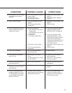
LIMIT AND AUXILIARY
SWITCHES
Complete switch assemblies may be replaced.
It is not possible to replace individual switches. To
replace switch assemblies, remove the top cover
(15/16” bolt head). Remove the #6-32 socket
head cap screws holding the switch assembly to
the plate.
Transfer the wires one at a time to the
replacement assembly using the push-on lugs
provided. Install the replacement assembly and
note that it rotates around one screw to permit
an adjustment of the cam-to-roller spacing and
switch operating point. To properly set the switch,
use a .030” shim between the cam and switch
lever and loosely position the switch assembly so
that the switch is just actuated. The switch lever
should be on the low or minimum radius portion
of the cam when setting the switches. DO NOT
overstress the switch lever. Tighten both screws
to 10 Ib-in torque and remove the shim. When
properly adjusted, the switch lever should remain
in contact with the cam throughout the control
drive travel.
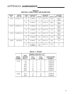
ADDING SWITCHES
It is possible to add up to four switches to
a control drive in the field. Consult the factory,
giving the control drive model and serial number
so that a correct list of parts required may be
supplied to you.
Remove the top cover (15/16” bolt head).
Install wiring onto the switch push-on lugs and
route the wires into the control drive terminal
area. Remove the terminal cover and solder
wires to the underside of the terminal assembly
according to the wiring diagram included with
the new switch assembly. Install the new switch
assembly and adjust according to the instructions
above. See Table 5, page 40, for switch assembly
part numbers.
SLM FRICTION SURFACE
In normal service, the SLM friction surface
will last for five to ten years. Faster rates of wear
can occur in any drive operating near its rated
thrust and with a frequency of operation greater
than one per minute on a 24 hour schedule. The
following procedure can be used to determine
the amount of wear life remaining on the friction
surface.
MAINTENANCE COMPONENT REPLACEMENT
Turn the Handswitch to STOP. Carefully turn
the Handwheel back and forth. If there is free
play in the Handwheel (up to one tenth of a full
Handwheel rotation) the SLM has sufficient wear
life. If there is no free play in the Handwheel,
the drive may not hold position and the friction
surface may need to be replaced—contact the
factory for details.
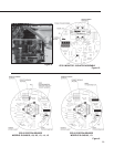
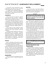
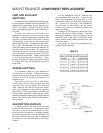
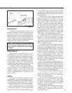
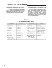
Damage to the SLM may require the SLM
Rebuild Kit shown in Table 4, below. The SLM
Rebuild Kit consists of a spring, spring pin, thrust
bearing, pinion, steel balls, locking disc, steel
shims, control motor gasket, terminal joints, and
instruction sheet.
See Figure 12, below, for identification of
typical SLM components.
TABLE 4
Figure 12