


5
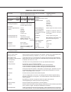
GENERAL SPECIFICATIONS
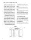
Model 120 V ac 240 V ac
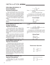
Max. Current 14-100 .56 A 72 W .33 A 80 W
and Power 14-200 1.5 A 180 W .86 A 210 W
Operating Temperature -40 to 85°C. (-40 to 185°F.)
0 to 99% relative humidity
Input Signal
Electronic Signal Receiver 0–5 mA
(ESR-4) 1–5 mA
4–20 mA
10–50 mA
1–5 V dc
-10 to 10 V dc
Input Signal Span Adj. 2 to 18 V dc
Input Signal Zero Adj. -100 to 275% of span
(except -10 to 10 V dc)
Split Signal Range 4–12 mA
12–20 mA
Deadband 0.6% of span
Sensitivity 25% of deadband
Direct AC Control 120 V ac for 2-position, multi-
position or modulating V ac
control.
Feedback
Contactless Position Sensor
(CPS-2)
Feedback Signal 1–5 mA
4–20 mA
10–50 mA
1–5 V dc
0–16 V dc
-10 to 10 V dc
Output Stability for 0.25% of span from 102 to 132 V ac
V ac Input Power
Output Stability for ±0.03%/°C. of span for 0 to 50° C.
Temperature Change ±0.05%/°C. of span for -40 to 85° C.
Linearity ±1% of span *
Hysteresis 0.25% of span at any point
Isolation Max. leakage of 10μA at 60 V rms,
60 Hz from output to ground
Film Potentiometer 1,000 ohms
Max. Voltage 40 V
Wattage 2 watts max.
Linearity ±0.5% *
Max. Wiper Current 1 mA
Input Power 120 V ac single phase 50 or 60 Hz; 48, 72 or 180 watts Allowable Tolerance
240 V ac single phase 50 or 60 Hz +10%, -15%
Action on Loss of Power Stays in place.
Action on Loss of Input Stays in place or moves to full travel or zero position. Drives to any preset position with
Signal (Power On) optional switch assembly on Models 14-_07 and 14-_08. Field adjustable.
Stall Protection and If the motor tries to run in one direction for more than 300 seconds, the Stall Protection
Annunciation (14-200 standard, Module shuts off power to the motor and a solid state relay will change state. The relay
14-100 optional) is rated for 120 V ac or dc, 10 VA.
Limit Switches Two SPDT, one for fully retracted and one for fully extended limit of travel.
Auxiliary Switches Up to four 6A, 120 V ac switches available.
Switches are labeled S1 to S4 and are cam operated, field adjustable.
S1 and S4 are set to operate just before reaching fully extended travel limit.
S2 and S3 are set to operate just before reaching fully retracted travel limit.
Handswitch Permits local electrical operation, independent of controller signal. Standard on all units.
An optional auxiliary contact can be used to indicate that the Handswitch is in AUTO
mode. Contact rated at 2.5 A, 125 V ac.
Handwheel Provides manual operation without electrical power.
Motor 120 V ac, single phase, no burnout, non-coasting motor has instant magnetic braking.
Requires no contacts or moving parts. Can remain stalled for 4 days without failure of
motor or gearing.
Gear Train High efficiency, precision cut steel and ductile iron gears and bronze nut.
Interchangeable gear modules permit field change of timing.
Mechanical Stops Prevent overtravel during automatic or manual operation.
Enclosure Precision machined aluminum alloy castings, painted with corrosion resistant polyurethane
paint, provides a rugged, dust-tight and weatherproof enclosure.
Stroke Adjustment Calibar simultaneously adjusts the stroke length, position feedback signal, limit switches
and auxiliary switches. The new stroke displacement is produced by the full input signal.
* Electrical linearity. Actual feedback relative to output shaft position varies with shaft position up to 15% at the center of stroke range.
Consult factory for details.