


23
Setting Auxiliary Switches
Standard switch settings for drives with 2 or
4 auxiliary switches are shown on the diagram
on page 22. The operating point of all auxiliary
switches is defined as a percentage of output
shaft travel. 100% is defined as the retracted
limit of shaft travel. The heavy line indicates
a closed circuit. Follow these instructions to
change the operating point of auxiliary switches:
NOTE: In the following procedure, it is assumed
that switch settings are to be adjusted so that
contacts are open when the desired position is
achieved. If they are to be adjusted to close,
it may be necessary to reverse the operating
mode of the switch by reversing the leads on
the switch itself. Be sure to disconnect power
from the switch terminals first.
1. Remove the top cover (15/16" bolt head).
The O-ring seal will remain in the rim of the
cover when removed. Open the terminal
block cover (1/2" bolt heads).
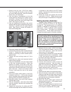
2. Use the electric Handswitch to drive the shaft
so that the switch cam is accessible. Using
a 7/64” hex wrench, loosen the screw so that
the cam is just snug on the shaft.
3. Move the output shaft to the desired position.
4. Disconnect power from the drive.
5. Connect the continuity meter across the
appropriate terminals. See the chart on
page 22 or the drive wiring diagram. Rotate
the cam until the meter shows no continuity
(switch contacts open, switch clicks).
6. Tighten the cam locking screw to 5 Ib-in
torque.
7. Disconnect the meter and reconnect power.
8. Move the drive’s output shaft in the desired
direction so that the cam lobe moves away from
the switch lever. If not correct, return to step 2
and reset the cam to the proper orientation.
9. Reconnect the meter.
10. Move the output shaft again toward the
desired switch position. If the contacts open,
the switch is properly set.
11. Close covers and tighten the terminal cover
bolts to 10 Ib-ft torque. Tighten the top cover
just enough to compress the O-ring seal.
1. Remove the top cover (15/16" bolt head).
The O-ring seal will remain in the rim of the
top cover when removed. Open the terminal
block cover (1/2" bolt head).
2. Use the electric Handswitch to drive the
control shaft so that the EXT switch cam is
accessible. Using a 7/64" hex wrench, loosen
the screw so that the cam is just snug to the
shaft. See Figure 5, page 22.
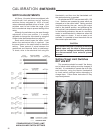
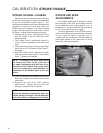
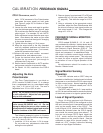
3. Use the Handwheel to position the control
shaft so that the lever of the sector-lever gear
assembly is parallel with the upper bearing
plate. See Figure 6, below for location of
lever and bearing plate.
4. Disconnect power from the drive.
5. Connect the continuity meter across terminals
B and V. Rotate the cam until the meter
shows no continuity (a switch contact opens;
switch clicks).
6. Tighten the cam locking screw to 5 Ib-in
torque.
7. Disconnect the meter and reconnect switch
wires and drive power.
8. Using the Handswitch, drive the output shaft
to the fully retracted position. Note the
direction of rotation of the lobe of the cam.
The correct cam lobe motion is away from the
switch lever with the switch lever on the lower
part of the cam. If this is not correct, return
to step 2 and reset the cam to the proper
orientation.
9. Drive the output shaft again to the fully
extended travel limit. If the correct stopping
point is reached (lever parallel with the upper
bearing plate), the switch is properly set.
10. Manually position the control shaft position
indicator dial to zero.
11. With the Handswitch, move the control shaft
until the position indicator dial reaches the
150° position.
12. Repeat the instructions for setting the RET
travel limit except that the direction of motion
is opposite to that used for the EXT switch
setting. Connect the continuity meter across
terminals B and U.
13. Close the covers and tighten the terminal
cover bolt to 10 Ib-ft. Tighten the top cover
bolt just enough to compress the O-ring seal.
FFigure 6