


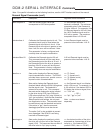


78
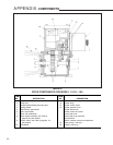
To remove the CPS-2:
1. Run the control drive to its midpoint of travel
with the local Handswitch. (If the standard
rotation of 100° has been reduced to 80°, the
midpoint of travel is 40°.)
2. Disconnect 120 V ac power to the drive.
Remove the terminal, DCM-2 compartment
and control end covers (1/2" bolt heads).
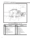
3. Record the wire colors on the terminal block
of the CPS-2 (see illustration at right), then
disconnect the wires. The terminals are
spring-loaded. To remove a wire, press the
tip of a small screwdriver into the slot at the
top of the small lever. Push down to open the
spring-loaded contact and release the wire.
4. Pull the wires from the transformer (see
illustration at right) back through the wire hole
in the CPS-2.
5. Loosen and remove the 3 hex studs that
clamp the CPS-2 in place. Ensure that the
inboard hex stud is not loosened as the
outboard stud is loosened.
6. Slide the CPS-2 stator assembly off the three
mounting bolts.
7. Note the position of the rotor clamp, then
loosen the rotor clamp screw and remove the
rotor from the shaft.
To install the new CPS-2:
1. Remove the rotor from the replacement
CPS-2 assembly. Slide the rotor, clamp end
first, onto the control shaft as close to the
mounting plate as possible. Leave the clamp
loose. Position the clamp in the same general
location as the one removed previously.
2. Slide the new CPS-2 assembly over the studs
and rotor. Replace the hex nuts but do not
tighten. Carefully slide the rotor back into the
CPS-2 assembly. Twist the rotor while sliding
to prevent damage to the assembly. Tighten
hex nuts to 5 Ib-ft (7 N•m).
3. Thread the wires through the wire holes in the
CPS-2 and reconnect them to the transformer
and terminal block.
4. Restore 120 V ac power to the drive and
connect a meter to the output.
5. Insert a 0.031" (.80 mm) feeler gauge between
the rotor clamp and stator. Position the clamp
0.031" (.80 mm) from the stator.
6. Rotate the rotor (only a minor adjustment
should be necessary) on the control shaft
until the output voltage measured across TP4
and TP1 (see illustration at right) reads 50%
(approx. 3 volts) of the signal span. Tighten
clamp to 5 lb-in (.6 N•m) torque.
7. Perform a position calibration procedure as
described on page 30 or page 54.
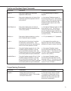
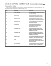
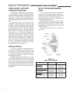
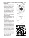
CPS-2 Components
Location of DCM-2 Test Points and Resistor
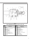
MAINTENANCE COMPONENT REPLACEMENT
POSITION
DEMAND
TRQ/THRUST
STALL
FB OPEN
STOP/LIMIT
ACKNOWLEDGE
TEMP F
CALIBRATE
SETPOS
100%
SETDEM
100%
SETDEM
0%
SETPOS
0%
R
FWD
REV
STAT
PWR
TP4
TP1
R11
TP3TP2
FUSE
F1