


29
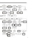
Split Range Operation
It is sometimes desirable or necessary to have
more than one final control element controlling a
single process. Often, this type of control strategy
requires that two to four Beck drives each respond
to different portions of one 4–20 mA Demand signal
from the control system.
This type of operation is called split range
operation. For example, consider the most
common split range scenario—two drives split
ranged for 50% of the 4–20 mA Demand signal
input. Both drives are wired in parallel to receive
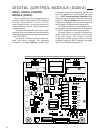
the same 4-20 mA signal (note that the 250 Ohm
R11
resistor (see DCM-2 illustration on page
78) must be removed from one of the two drive
DCM-2 boards to allow HART
®
communications.
If more than two drives are split ranged, the R11
resistor must be removed from all the DCM-2
boards but one), but each drive’s interpretation
of the signal must be different. One drive must
interpret 4–12 mA as 0–100% Demand, and
one drive must interpret 12–20 mA as 0–100%
Demand. This requires that the drives have
different Demand signal calibrations.
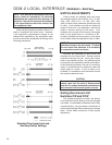
To set up a split range operation, follow the
steps listed below (see page 24 for location of
pushbutton controls).
NOTE: Ensure that the L.O.S. (Loss of
Demand input signal) settings of the drives are
appropriate for the configuration. See page 21
for information on changing L.O.S. settings.
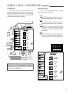
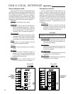
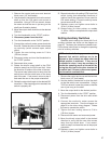
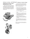
1. Remove the DCM-2 cover (1/2” bolt heads).
2. Ensure the Handswitch is in the “STOP”
position. This will prevent the drive from
repositioning during this procedure.
3. Apply the desired 0% Demand input signal to
the drive. (Following the example above, the
minimum signal for the first drive would be 4
mA. The second drive’s minimum signal would
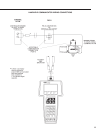
be 12 mA). If the drive has not been wired, the
Demand input signal is connected at terminals
AA (+) and BB (–) as shown in the diagram on
page 17.
4. Press and hold the “CALIBRATE” pushbutton
on the DCM-2 customer interface panel, then
press the “SET DEM 0%” pushbutton until the
“ACKNOWLEDGE” LED is lit.*
5. Apply the desired 100% Demand input signal
to the drive. (Following the example above,
the maximum signal for the first drive would be
12 mA. The second drive’s maximum signal
would be 20 mA).
Demand Square Function
Input Actual Output
Signal Standard Output Position
(mA) (% of Span) (% of Span)
4.0 0 0
5.6 10 1
12.0 50 25
15.2 70 49
18.4 90 81
20.0 100 100
6. Press and hold the “CALIBRATE” pushbutton
on the DCM-2 customer interface panel, then
press the “SET DEM 100%” pushbutton until
the “ACKNOWLEDGE” LED is lit.*
7. Repeat this process for the remaining drives
to be split-ranged.
8. Run the drive through its full operating range to
ensure proper response to the Demand input
signal.
9. Replace the DCM-2 cover. Tighten the cover
bolts to 10 lb-ft (14 N•m) torque.
* If the “ACKNOWLEDGE” LED does not light, but
the “DEMAND” LED does light, the signal is out
of acceptable range and was not accepted by
the DCM-2. This is typically caused by trying to
set 0% and 100% values too close together (i.e.,
less than 4 mA difference).
Square Function
Beck drives can be set up to position the output
shaft proportionally to the square of the Demand
input signal (see table below). This function is
factory configurable, or may be configured using
the HART or Serial interface.