


27
1. Remove the control end cover and terminal
block cover (1/2" bolt heads).
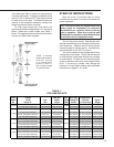
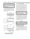
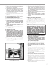
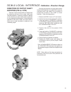
2. Use the electric Handswitch to drive the control
shaft so that the CW switch cam screw is
accessible. Using a 7/64" hex wrench, loosen
the screw so that the cam is just snug on the
shaft (see illustration below).
3. Move the output shaft clockwise to the desired
CW limit.
4. Turn the Handswitch to the “STOP” position.
5. Disconnect power from the drive.
6. Turn the Handswitch to the "AUTO" position.
7. Connect the continuity meter across terminals
B and M. Rotate the cam until the meter shows
no continuity (switch contacts open, switch
clicks).
8. Tighten the cam locking screw to 5 Ib-in
(.56 N•m) torque.
9. Disconnect meter and turn the Handswitch to
the "STOP" position.
10. Reconnect drive power.
11. Rotate the drive’s output shaft in the CCW
direction away from the CW travel limit. Note
the direction of rotation of the lobe of the cam.
The correct cam lobe motion is away from the
switch lever with the switch lever on the lower
part of the cam. If not correct, return to step 2
and reset the cam to the proper orientation.
12. Rotate the output shaft again to the desired CW
travel limit. If the stopping point is reached, the
switch is properly set.
13. Repeat instructions for setting CCW travel limit
switch (noting that referenced directions of
rotation should be opposite of those used for
CW switch setting). Connect continuity meter
across terminals B and N.
14. Replace covers and tighten cover bolts to
10 Ib-ft (14 N•m) torque.
15. Rotate index (or index pointer on models
11-159 or -169) to correspond with output shaft
rotation.
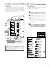
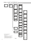
Setting Auxiliary Switches
Standard switch settings for drives with 2 or 4
auxiliary switches are shown on the diagram on
page 26. The heavy line indicates a closed circuit.
Follow these instructions to change the operating
point of auxiliary switches:
NOTE: In the following procedure, it is
assumed that switch settings are to be
adjusted so that contacts are open when the
desired position is achieved. If they are to
be adjusted to close, it may be necessary to
reverse the operating mode of the switch by
moving the wire lead to the other terminal on
the switch itself. Be sure to disconnect power
from the switch terminals first.
1. Remove the control end cover and the terminal
block cover (1/2" bolt heads).
2. Use the electric Handswitch to drive the shaft
so that the switch cam is accessible. Using a
7/64" hex wrench, loosen the screw so that the
cam is just snug on the shaft.
3. Move the output shaft to the desired position.
4. Turn the Handswitch to the “STOP” position.
5. Disconnect power from the drive and switch
terminals.
6. Connect the continuity meter across the
appropriate terminals. See the diagram on
page 26 or the drive wiring diagram. Rotate
the cam to operate the switch.
7. Tighten the cam locking screw to 5 Ib-in
(.56 N•m) torque.
8. Disconnect the meter and reconnect power.
9. Move the drive’s output shaft in the desired
direction to verify that the cam lobe moves
away from the switch lever. If not correct,
return to step 2 and reset the cam to the proper
orientation.
10. Replace covers and tighten cover bolts to
10 Ib-ft (14 N•m) torque.
Loosening Switch Cam