


42
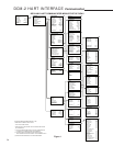
DCM-2 HART INTERFACE Communication
3. Identify Device - This command will cause the
Acknowledge LED to blink for two seconds.
Used to verify proper HART communications
as well as an aid in identifying which drive is
being addressed when configuring multiple
drives for split range operation.
4. Board reset - This procedure resets the
board without powering down the drive. There
are many communicator procedures that
implement the reset procedure automatically
to ensure the proper initialization of the DCM-
2 board; however, manually implementing the
reset procedure is not typically necessary.
CW Torque Submenu
(Block 4J)
This menu displays the torque applied over
ten segments of travel of the drive shaft.
CCW Torque Submenu
(Block 4K)
This menu displays the torque applied over
ten segments of travel of the drive shaft.
Alarm Setup Submenu
(Block 4L)
This menu allows customization of alarm
indication:
1. AlarmPol - This determines whether the alarm
relay "Drops Out" or "Pulls In" to indicate an
alarm.
2. Alarm Mask - This leads to a submenu where
alarm conditions may be set.
Alarm Mask Submenu
(Block 5H)
This menu allows alarm conditions
to be ignored; such as DemandLOS, Stall
FeedbackLOS, or other conditions which may
occur under normal operation and that may prove
a nuisance during normal HART operation.
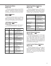
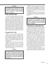
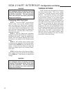
CW Inhibitors Submenu
(Block 5F)
This menu displays the ON or OFF status of the
contributing sources of retract movement inhibitors
of motor operation: Balance, Supervisory, Stall,
OverTrq/Thr, Switch Block, Bad Pos Sig, Bad Dem
Sig, Local Cal. See below.
CCW Inhibitors Submenu
(Block 5G)
This menu displays the ON or OFF status of the
contributing sources of extend movement inhibitors
of motor operation: Balance, Supervisory, Stall,
OverTrq/Thr, Switch Block, Bad Pos Sig, Bad Dem
Sig, Local Cal. See table above.
Tests Submenu
(Block 4I)
This menu provides procedures that allow the
user to test, identify and reset the DCM-2 board.
They are as follows:
1. FB out test - This procedure allows the user
to test the 4–20 mA position feedback output
signal. Following the prompts through this
procedure allows the user to physically verify
the output signal value at 4 mA, 20 mA, and
anywhere in between.
2. Board self-test - This procedure runs an
automatic board test that verifies the health of
the DCM-2 control board. It runs a checksum
memory test and checks for the proper
installation of the position sensor (CPS rotor).
Running the test causes the drive to reposition
temporarily, so it should only be run offline.
The CPS test runs automatically as part of
some calibration and setup procedures. This
test should be implemented only if a DCM-2
problem is suspected.
CONDITION DESCRIPTION
Balance "ON indicates that the Demand and
Position are at balance"
Supervisory "ON indicates that the DCM is
initializing"
Stall "ON indicates a Stall condition"
OverTrq/Thr "ON indicates that the motor is stopped
due to excessive torque or thrust"
Switch Block "ON indicates that the Handswitch,
Override, or Limit Switch is inhibiting
movement"
Bad Pos Sig "ON indicates that the Position signal
is out of range"
Bad Dem Sig "ON indicates that the Demand signal
is out of range"
Local Cal "ON indicates that a Local Calibration
button is pressed"