


76
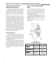
OVER-TRAVEL LIMIT AND
AUXILIARY SWITCHES
Complete switch assemblies may be replaced.
It is not possible to replace individual switches.
To replace switch assemblies, remove the control
end cover (1/2" bolt heads) and extensions, if
applicable. Remove the screws holding the
switch assembly to the plate and slide it out to the
side.
Transfer the wires one at a time to the
replacement assembly using the push-on lugs
provided. Install the replacement assembly and
note that it rotates around one screw to permit
an adjustment of the cam-to-switch lever spacing
and switch operating point. To set the switch,
place a .030" (.75 mm) shim between the cam
and switch lever. The switch lever should be
on the low or minimum radius portion of the cam
when setting the switches. Position the switch
assembly so that the switch is just actuated. DO
NOT overstress the switch lever. Tighten both
screws to 10 Ib-in (14 N•m) torque and remove
the shim. When properly adjusted, the switch
lever should remain in contact with the cam
throughout the control drive travel.
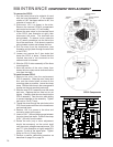
Adding Switches
It is usually possible to add switches to a
control drive in the field. Remove the control
end cover (1/2" bolt heads). If the drive has
no auxiliary switches, it is possible to add up to
four switches. See Table 4, page 79, for switch
assembly part numbers.
Install wiring onto the switch push-on lugs
and route the wires into the control drive terminal
area. Remove the terminal cover and solder
wires to the underside of the terminal assembly
according to the wiring diagram included with
the new switch assembly. Install the new switch
assembly and adjust according to the preceding
instructions.
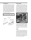
SELF-LOCKING MECHANISM
(SLM)
In normal service, the SLM friction surface
should not require replacement; however, a
combination of excessive modulation and load
can cause wear to the SLM mechanism. If
the SLM has been damaged, rebuild kits are
available (see Table below).
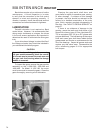
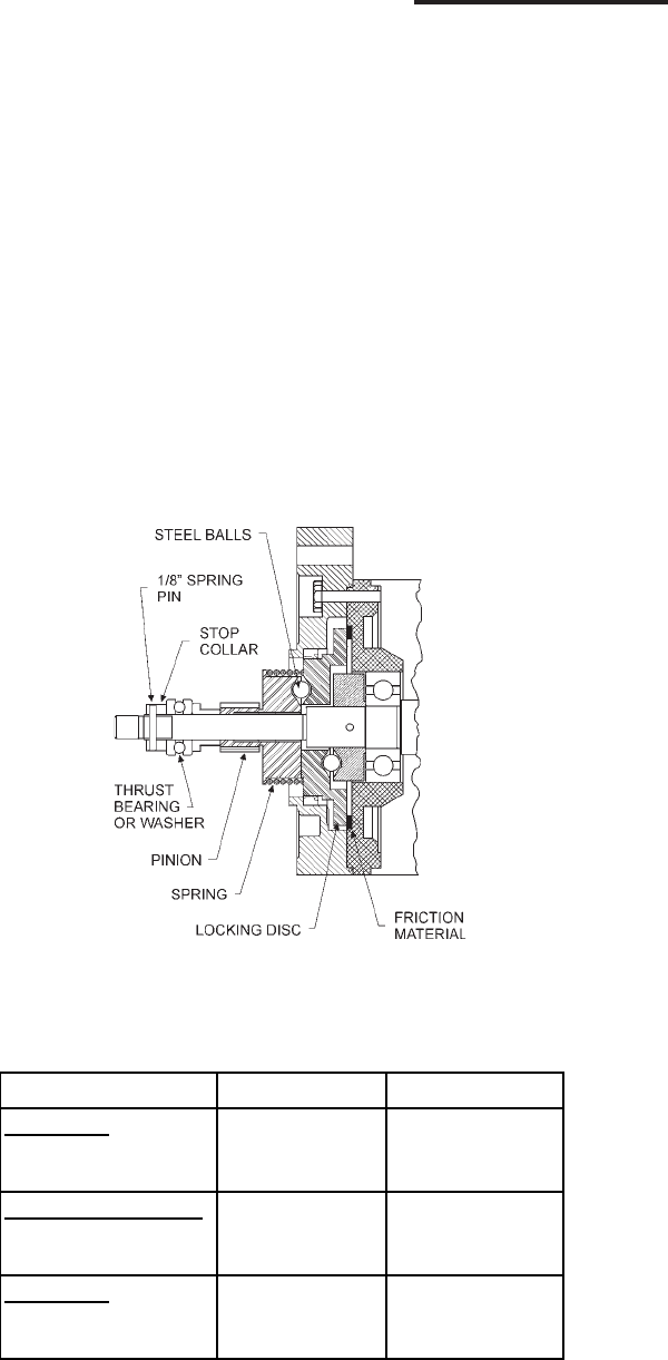
SLM Rebuild Kits typically consist of friction
material, spring, spring pin, thrust washer, pinion,
steel balls, locking disc, steel shims, control
motor gasket, terminal joints, slip-on terminal and
instruction sheet.
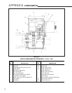
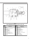
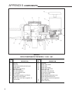
See the illustration below for component
identification.
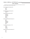
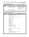
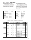
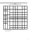
TABLE 3:
SLM PART NUMBERS
Motor Part Number SLM Rebuild Kit Instruction Sheet
11-159/-169
20-2700-20 12-8060-15 80-0016-05
20-2701-20 12-8060-16 80-0016-05
11-209/-269, -309/-369
20-2704-21 12-8060-17 80-0016-07
20-2705-21 12-8060-18 80-0016-07
11-409/-469
20-2201-21, -22, -23 12-8060-11 80-0016-01
20-2201-31, -32, -33 12-8060-13 80-0016-02
MAINTENANCE COMPONENT REPLACEMENT