


28
DEMAND CALIBRATION
DCM-2 boards are designed to accept a
4–20 mA (or 1–5 V dc) analog demand signal.
Narrower spans within this range can also be
accommodated for split range operation (see page
29). The input comes calibrated from the factory
for the full range unless otherwise specified by
the customer. It is not necessary to calibrate the
Demand input when the drive is installed; however,
it can be easily accomplished using the DCM-2
pushbutton controls (or HART or Serial interface)
and a signal source. Following this procedure
is only necessary to compensate for slight
differences between the signal source calibration
and the DCM-2 factory calibration, or if reduced
range calibration is desired for special operating
scenarios such as split ranging.
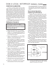
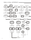
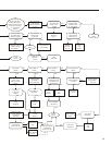
Calibration Procedure
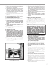
1. Remove the DCM-2 cover (1/2” bolt heads).
2. Ensure the Handswitch is in the “STOP”
position. This will prevent the drive from
repositioning during this procedure.
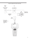
3. Apply the desired 0% Demand input signal to
the drive (e.g., 4 mA for 4–20 mA input). If the
drive has not been wired, the Demand input
signal is connected at terminals AA (+) and BB
(–) as shown in the diagram on page 17.
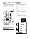
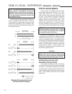
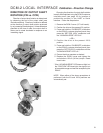
4. Press and hold the “CALIBRATE” pushbutton
on the DCM-2 customer interface panel, then
press the “SET DEM 0%” pushbutton until the
“ACKNOWLEDGE” LED is lit.*
5. Apply the desired 100% Demand input signal
to the drive (e.g., 20 mA for 4–20 mA input).
6. Press and hold the “CALIBRATE” pushbutton
on the DCM-2 customer interface panel, then
press the “SET DEM 100%” pushbutton until
the “ACKNOWLEDGE” LED is lit.*
7. Turn the Handswitch to the “AUTO” position.
NOTE: The drive may reposition.
8. Run the drive through its full operating range to
ensure proper response to the Demand input
signal.
9. Replace the compartment covers and tighten
the cover bolts to 10 lb-ft (14 N•m) torque.
* If the “ACKNOWLEDGE” LED does not light, but
the “DEMAND” LED does light, the signal is out
of acceptable range and was not accepted by
the DCM-2. This is typically caused by trying to
set 0% and 100% values too close together (i.e.,
less than 4 mA difference).
DCM-2 LOCAL INTERFACE Calibration - Demand