


30
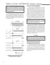
POSITION CALIBRATION
In order to correctly position the drive output
shaft in response to the Demand input signal, the
DCM-2 receives a position signal from the drive’s
position sensor and compares this actual position
to the Demand input. This process requires that the
DCM-2 interprets the position signal appropriately
for the full range of desired travel. This procedure
will calibrate the DCM-2 to accept the position signal
and interpret the appropriate 0–100% range. Note
that all drives come factory calibrated and there is
no need to recalibrate unless changes in operation
are desired.
It is also possible to calibrate the position signal
using the HART or Serial interface.
Short-stroke Operation
(Reducing Full Rotation)
Typically, it is best to use the full 100° (or 90°
for quarter-turn valve drives) rotation of the drive
in response to the 0–100% Demand input signal—
this allows full flexibility in arranging the drive’s
torque to be distributed for the best mechanical
advantage relative to the driven load.
In certain applications, as a last resort, it may
become necessary to reduce the full rotation of
the drive. In these applications, the DCM-2 can be
calibrated to accommodate reduced stroke. The
recommended minimum full stroke rotation is 60°
(although it is advisable to make the range as close
to 100° (or 90°) as possible for the highest position
resolution attainable with the CPS and to avoid
reduction in torque (linkage connected drives); if
the driven element stroke rotation is less than 100°
(where applicable), a linkage can be used to allow
the driven element to move the correct rotation
while still allowing the drive to rotate 100°).
To reduce the full rotation of the drive (short-
stroke), use the customer interface panel and
follow the "position calibration" instructions (this
page). Short-stroking can also be accomplished
by using the HART (see page 55) or Serial (see
page 71) interface.
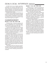
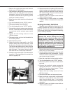
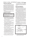
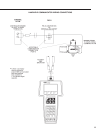
The illustration below represents a Beck drive
with linkage requiring an 80° full stroke rotation.
(Please note that the crank arm may be adjusted
to any start angle orientation).
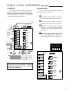
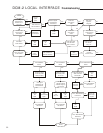
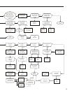
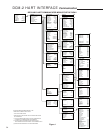
DCM-2 LOCAL INTERFACE Calibration - Position
Calibration Procedure
NOTE: Prior to adjusting the travel range
electronically (using the DCM-2), it is
recommended that the over-travel protection
switches be reset just outside the intended
travel range (see page 26).
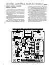
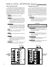
1. Remove the DCM-2 cover (1/2” bolt heads).
2. Position the drive at the desired minimum
position (i.e., the desired physical position of
the drive’s output shaft corresponding to the
0% Demand input signal).
3. Ensure the Handswitch is in the “STOP”
position. This will prevent the drive from
repositioning during this procedure.
4. Press and hold the “CALIBRATE” pushbutton
on the DCM-2 customer interface panel, then
press the “SET POS 0%” pushbutton until the
“ACKNOWLEDGE” LED is lit.*
5. Position the drive at the desired maximum
position (i.e., the desired physical position of
the drive’s output shaft corresponding to the
100% Demand input signal).
6. Ensure the Handswitch is in the “STOP”
position. This will prevent the drive from
repositioning during this procedure.
7. Press and hold the “CALIBRATE” pushbutton
on the DCM-2 customer interface panel, then
press the “SET POS 100%” pushbutton until
the “ACKNOWLEDGE” LED is lit.*
8. Optional: Adjust the over-travel limit switches (see
page 26) just outside the 0% and 100% limits.
9. Verify that the drive’s 0% and 100% positions
are correct. If not, repeat this procedure.
10. Replace the compartment cover and tighten
the cover bolts to 10 lb-ft (14 N•m) torque.
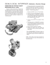
Crank arm may be adjusted to any start angle orientation.
The orientation shown above has been randomly
selected for the purpose of this example.
NOTE:
* If the “ACKNOWLEDGE” LED does not light, but
the “POSITION” LED does light, the signal is out
of acceptable range and was not accepted by the
DCM-2.