


44
DCM-2 HART INTERFACE Configuration and Setup
All drives are shipped completely configured
to the customer’s specifications and are ready
to be installed. If the need arises to change
the configuration of the drive (i.e., change
one or more of the setup parameters that
define how the drive operates), this may be
accomplished utilizing the HART
®
interface
and a communications tool (model 275 or 375
HART
®
Communicator) as described in the
Communications section of this manual. This
section of the manual covers how the drive is
configured and gives instructions for changing
each particular setup parameter available. It
is intended to build upon the Communications
Section, which provides a detailed description
of the HART
®
Menu Tree and defines all the
parameters and commands. If unfamiliar with
the HART
®
communicator and Beck drives,
please review the Communications section
before proceeding.
There are a number of configuration setup
parameters that can be changed to custom tailor
the drive’s operation to the application needs. The
remainder of this section provides instructions
for changing each of these parameters. The
instructions below assume that the user has a
model 275 HART
®
Communicator attached to the
Demand wiring (at drive terminals AA and BB or
anywhere across the wires all the way back to the
source of the Demand signal), has established
communications with a particular drive, and has
a copy of the HART
®
Menu Tree (Figure 1, page
34) available.
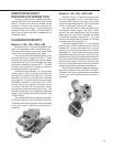
DRIVE SHAFT TRAVEL
Drive shaft travel refers to the direction the
output shaft of the drive moves in response to
an increasing Demand input signal. The travel
is either clockwise (CW) or counterclockwise
(CCW). The control loop operation and physical
design of the final control element determine
the drive travel suitable for an application. If
the drive travel needs to be changed, this is
easily accomplished by changing the DCM-2
configuration.
Changing Drive Shaft Travel
STEP 1 - From the HART
®
communicator
“Online” menu, move to the “General Setup”
menu and select the “Drive Dir” parameter. This
is accomplished by using the up and down arrow
keys to select the appropriate item in each menu
and then moving forward by pressing the right
arrow key. Follow the Menu Tree (Figure 1, page
34) to navigate.
STEP 2 - With the “Drive Dir” parameter
selected, press the right arrow key to display the
two entry choices: “CW incr” and “CCW incr”.
Use the up and down arrow keys to select the
desired parameter.
STEP 3 - With desired parameter selected,
push the F4 function key, which is defined as the
ENTER key at the bottom of the display. Pushing
this key enters the value and reverts the display
back to the “General Setup” main menu.
STEP 4 - At the bottom of the “General Setup”
menu, the F2 function key should now be defined
as the SEND key. Push this key to execute the
change.
WARNING
Carefully follow the on-screen warnings
and messages when proceeding, because
changing this parameter will cause the drive
to reposition. This can adversely affect the
process and cause potentially dangerous
conditions.
STEP SIZE
The step size is the incremental movement
of the drive shaft in response to signal changes.
The step size is factory set at 0.15% unless
otherwise specified at the time of order. The step
size is adjustable from 0.1% to 2.5%. To adjust
the step size, please follow the steps below.
Changing the Step Size
STEP 1 - From the HART
®
communicator
“Online” menu, move to the “General Setup”
menu and select the “StepSize” parameter. This
is accomplished by using the up and down arrow
keys to select the appropriate item in each menu
and then moving forward by pressing the right
arrow key. Follow the Menu Tree (Figure 1, page
34) to navigate.
STEP 2 - With the “StepSize” parameter
selected, press the right arrow key to display the
modifiable entry box, and using the alphanumeric
keypad, type in the desired dead band value.
Values between 0.1% and 2.5% are valid.
STEP 3 - With the desired value correctly
typed into the entry box, push the F4 function key
which is defined as the ENTER key at the bottom
of the display. Pushing this key enters the value
and reverts the display back to the “General
Setup” main menu.
STEP 4 - At the bottom of the “General Setup”
menu, the F2 function key should now be defined
as the SEND key. Push this key to execute the
change.