


23
DCM-2 LOCAL INTERFACE Operation
OVERVIEW
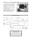
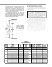
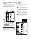
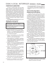
The DCM-2 customer interface panel (pictured
below) allows the user to easily calibrate the
drive and troubleshoot conditions. The following
information provides an overview of the DCM-2
customer interface panel features.
NOTE: Beck drives are shipped from the
factory set up and calibrated to customer
specifications placed at the time of order and
are ready for installation.
Overview LEDs
The four LEDs, as highlighted below, indicate
the present state of the drive.
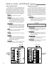
FWD
This LED is lit when the drive is receiving a
Demand signal greater than its position.
REV
This LED is lit when the drive is receiving a
Demand signal smaller than its position.
STAT
This LED is lit when additional status is
available. For details regarding possible
conditions, see “Status Indication LEDs”
on page 24.
PWR
This LED is lit when power is applied to the
drive. This LED pulses from bright to dim
indicating the DCM-2 is fully operational.
POSITION
DEMAND
TRQ/THRUST
STALL
FB OPEN
STOP/LIMIT
ACKNOWLEDGE
TEMP F
CALIBRATE
SET POS
100%
SET DEM
100%
SET DEM
0%
SET POS
0%
R
FWD
REV
STAT
PWR
POSITION
DEMAND
TRQ/THRUST
STALL
FB OPEN
STOP/LIMIT
ACKNOWLEDGE
TEMP F
CALIBRATE
SET POS
100%
SET DEM
100%
SET DEM
0%
SET POS
0%
R
FWD
REV
STAT
PWR