


16
INSTALLATION
INSTALLATION—MECHANICAL
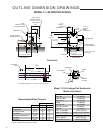
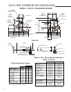
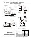
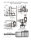
Beck Group 11 drives may be installed in
any convenient orientation, because the gearing
does not require an oil bath. Refer to the outline
dimension drawings on pages 8–14 for physical
dimensions and required clearances.
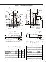
Installing a Drive with Linkage
When installing a Beck drive in a location
remote from the damper or valve, be sure it is firmly
bolted to a flat mounting surface that will not yield
to the stresses created from operating the device.
A rigid, vibration-free surface will generally prolong
the life of the drive’s components.
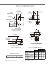
The output shaft of the drive should be parallel
to the damper or valve shaft, and the linkage
should be in a plane perpendicular to that of the
two shafts. Small misalignments can be tolerated
if a rod end fitting is used on the driven lever similar
to that on the Beck crank arm. The drive’s crank
arm can be positioned at any angle on the shaft.
Beck drives can be furnished with valves
mounted as unitized assemblies ready for pipeline
installation. Beck linkage kits are available for
convenient field installation (see page 5).
Installing a Direct-coupled Drive
CAUTION
Whenever a control drive is being mounted on
a valve, it is good practice to remove the valve
from service and observe these precautions:
• Know what fluid is in the line.
• Wear proper protective equipment.
• Disconnect electrical power.
• Depressurize the pipeline.
• Refer to the valve maintenance manual for
specific instructions.
• Consult the Beck Valve Mounting
Specification sheet shipped with the drive
for instructions.
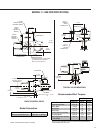
Installing a Unitized Valve/Drive
Assembly on a Pipeline
Inspect the valve and pipe flanges to ensure
they are clean. Be certain that other pipelines in
the area are free from pipe scale or welding slag
that could damage the gasket surfaces.
Carefully lift the assembly and position the
valve in the pipeline. Install and tighten the
flange bolts according to the valve and/or gasket
manufacturer’s instructions.
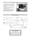
INSTALLATION—ELECTRICAL
NOTE: All Beck drives are shipped from the
factory ready for installation; no electrical
adjustments are required before placing
them in operation. Each drive is set up and
calibrated to the customer’s specifications that
were written into the equipment order.
Two N.P.T. conduit connections are provided
for power and signal wiring to the drive. The 1/2"
conduit is provided for signal wiring connections, and
the 1" conduit is provided for power and auxiliary
switch connections. A sealant must be used on
threaded conduit connections to keep moisture out.
Conduits should be routed from below the drive so
that condensation and other contaminants entering
the conduit cannot enter the drive.
Power and signal wires must be routed to the
drive separately and be either shielded cables or
installed in conductive conduit and/or cable trays.
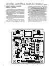
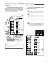
A large, clearly labeled terminal block on the
top of the drive is enclosed in a separate, gasketed
metal enclosure. Terminals will accommodate up
to 12 AWG (3.31 mm
2
) wiring. See page 4 for
location of the terminal block.
CAUTION
Always close covers immediately after
installation or service to prevent moisture or
other foreign matter from entering the drive.
Refer to the wiring diagram furnished with
your Beck drive for proper AC power and signal
connections. It is advisable to provide normal short
circuit protection on the AC power line. A copy of
the wiring diagram is shipped with each drive and
is fastened to the inside of the terminal block cover.
If there is no wiring diagram available, you may
obtain a copy from Beck by providing the serial
number of your drive.
Your Beck drive has been supplied to match
the signal source in your control loop. If it does not
match, a 250 ohm input resistor may be added or
removed to obtain the proper match. Consult the
factory for details.
For maximum safety, the Beck drive body
should be grounded. Use the grounding terminal
in the wiring compartment of the drive.
NOTE: The valve may have undergone
temperature variations in shipment. This
could result in seepage past the stem seals.
Refer to the valve manufacturer’s maintenance
instructions for packing adjustments.