


3
FC-21 Flow Computer
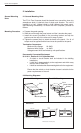
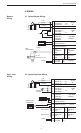
Relay Outputs
The relay outputs are menu assignable to
(Individually for each relay) Low Rate Alarm, Hi
Rate Alarm, Prewarn Alarm, Preset Alarm, Pulse
Output (pulse options) or General purpose warning
(security).
Number of relays: 2 (4 optional)
Contact Style: Form C contacts
Contact Ratings: 250 VAC @ 5 amps
30 VDC @ 5 amps
Fast Transient Threshold: 1000 V
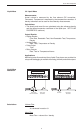
Serial Communication
The serial port can be used for printing, datalogging,
modem connection and communication with a
computer.
RS-232:
Device ID: 01-99
Baud Rates: 300, 600, 1200, 2400, 4800, 9600,
19200
Parity: None, Odd, Even
Handshaking: None, Software, Hardware
Print Setup: Configurable print list and formatting
RS-485:
Device ID: 01-247
Baud Rates: 300, 600, 1200, 2400, 4800, 9600,
19200
Parity: None, Odd, Even
Protocol: Modbus RTU (Half Duplex)
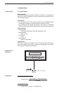
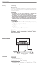
Analog Output
The analog output is menu assignable to
correspond to the Uncompensated Volume Rate,
Corrected Volume Rate, Mass Rate, Temperature,
Density, Volume Total, Corrected Volume Total or
Mass Total.
Type: Isolated Current Sourcing
Isolated I/P/C: 500 V
Available Ranges: 4-20 mA, 0-20 mA
Resolution: 12 bit
Accuracy: 0.05% FS at 20 Degrees C
Update Rate: 1 update/sec minimum
Temperature Drift: Less than 200 ppm/C
Maximum Load: 1000 ohms (at nominal line
voltage)
Compliance Effect: Less than .05% Span
60 Hz rejection: 40 dB minimum
EMI: No effect at 3 V/M
Calibration: Operator assisted Learn Mode
Averaging:User entry of DSP Averaging constant
to cause an smooth control action.
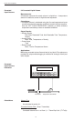
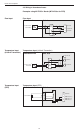
Isolated Pulse output
The isolated pulse output is menu assignable to
Uncompensated Volume Total, Compensated
Volume Total or Mass Total.
Isolation I/O/P: 500 V
Pulse Output Form: Open Collector
Maximum On Current: 125 mA
Maximum Off Voltage: 30 VDC
Saturation Voltage: 1.0 VDC
Maximum Off Current: 0.1 mA
Pulse Duration: User selectable
Pulse output buffer: 8 bit
Pulse Rate Averaging: Standard
Fault Protection
Reverse polarity: Shunt Diode
Transient Protection: 500 VDC
(Capacitive Clamp)
Operating Mode
The Flow Computer can be thought of as making a
series of measurements of flow, temperature/
density sensors and then performing calculations
to arrive at a result(s) which is then updated
periodically on the display. The analog output, the
pulse output, and the alarm relays are also updated.
The cycle then repeats itself.
Step 1:Update the measurements of input signals-
Raw Input Measurements are made at each input
using equations based on input signal type selected.
The system notes the “out of range” input signal as
an alarm condition.
Step 2:Compute the Flowing Fluid Parameters-
The temperature, viscosity, and density equations
are computed as needed based on the flow
equation and input usage selected by the user.
Step 3 : Compute the Volumetric Flow-
Uncompensated flow is the term given to the flow
in volume units. The value is computed based on
the flowmeter input type selected and augmented
by any performance enhancing linearization that
has been specified by the user.
Step 4: Compute the Corrected Volume Flow at
Reference Conditions-
In the case of a corrected liquid volume flow
calculation, the corrected volume flow is computed
as required by the selected compensation equation.
Step 5 : Compute the Mass Flow-
All required information is now available to compute
the mass flow rate as volume flow times density.
Step 6: Check Flow Alarms-
The flow alarm functions have been assigned to
one of the above flow rates during the setup of the
instrument. A comparison is now made by
comparing the current flow rates against the
specified hi and low limits.
Step 7: Compute the Analog Output-
This designated flow rate value is now used to
compute the analog output.
Step 8: Compute the Flow Totals by Summation-
A flow total increment is computed for each flow
rate. This increment is computed by multiplying the
respective flow rate by a time base scaler and then
summing. The totalizer format also includes
provisions for total rollover.
Step 9: Total Preset Comparisons-
The total associated with a preset function is then
compared against the corresponding preset value
and any required control actions taken.
Step 10: Pulse Output Service-
The pulse output is next updated by scaling the
total increment which has just been determined by
the pulse output scaler and summing it to any
residual pulse output amount.
Step 11: Update Display and Printer Output-
The instrument finally runs a task to update the
various table entries associated with the front panel
display and serial outputs.