


25
FC-21 Flow Computer
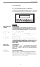
6.4.8
SETUP
FLOW INPUT
(Pulse - Ain & PS
(A=B))
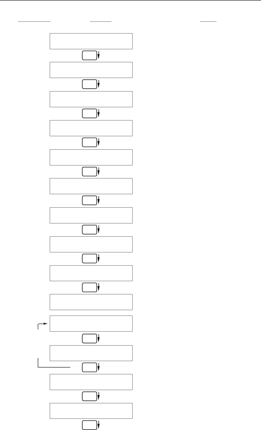
SETUP FLOW INPUT
EXCITATION VOLTAGE
5v 12v 24v
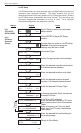
FLOW INPUT TYPE
Pulse Analog
PULSE INPUT TYPE
Ain PS(A=B) Qx1 Qx2
PULSE TRIGGER LEVEL
10mV 100mV 2.5V
LOW PASS FILTER
40Hz 3KHz 20KHz
INPUT TERMINATION
Pullup Pulldown None
MAX WINDOW (1-99)
1
K_FACTOR TYPE
Avg LinTbl UVC
AVERAGE KA-FACTOR
####### P/gal
LINEAR TABLE KA
Fre01:######## Hz
LINEAR TABLE KA
KA--01:####### P/gal
LOW FLOW RATE ALARM
####### gal/m
HIGH FLOW RATE ALARM
####### gal/m
Advance To
SETUP AUX INPUTS
ENTER
ENTER
ENTER
ENTER
ENTER
ENTER
ENTER
ENTER
ENTER
ENTER
ENTER
ENTER
ENTER
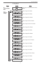
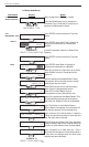
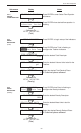
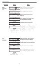
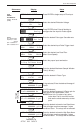
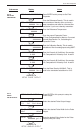
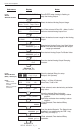
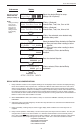
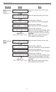
Press ENTER to begin setup of Flow Input.
Select the desired Excitation Voltage.
Press ENTER when Pulse is flashing to
configure the flow input for Pulse signals.
Enter the desired Pulse type. See side note.
Select the desired Input Pulse Trigger Level.
Select the desired Low Pass Filter.
(Max. Count Speed).
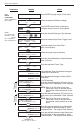
Select the proper input termination.
Enter the desired Maximum Sample Window
Time (1-99 sec).
Enter the desired K-Factor Type.
If Avg selected, Enter the desired Average K-
Factor.
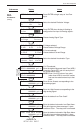
If LinTbl selected,
Enter the desired frequency/ K-Factor pair for
each point in the Linearization Table.
NOTE: Enter 0 for Fre value of any point
(other than Fre01) to exit the routine
and use the values entered up to that
point.
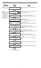
Enter the desired volumetric Low Rate Alarm.
This will trigger an alarm message if alarm
conditions occur. The relays are not affected.
Enter the desired volumetric High Rate Alarm.
This will trigger an alarm message if alarm
conditions occur. The relays are not affected.
Sub-menus Display Notes
Through
16 Points
NOTE:
Ain = Single Pulse
PS(A=B) = Pulse
Security
Qx1 = Quadrature
Qx2 = Quadrature x 2