


51
FC-21 Flow Computer
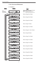
MENU
Sub-menus Display Notes
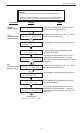
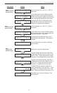
8.2.15
Calibrate 4mA Out
Submenu Group
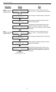
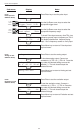
8.2.16
Calibrate 20mA Out
Submenu Group
ENTER
ENTER
ENTER
ENTER
STOP
ENTER
STOP
STOP
MENU
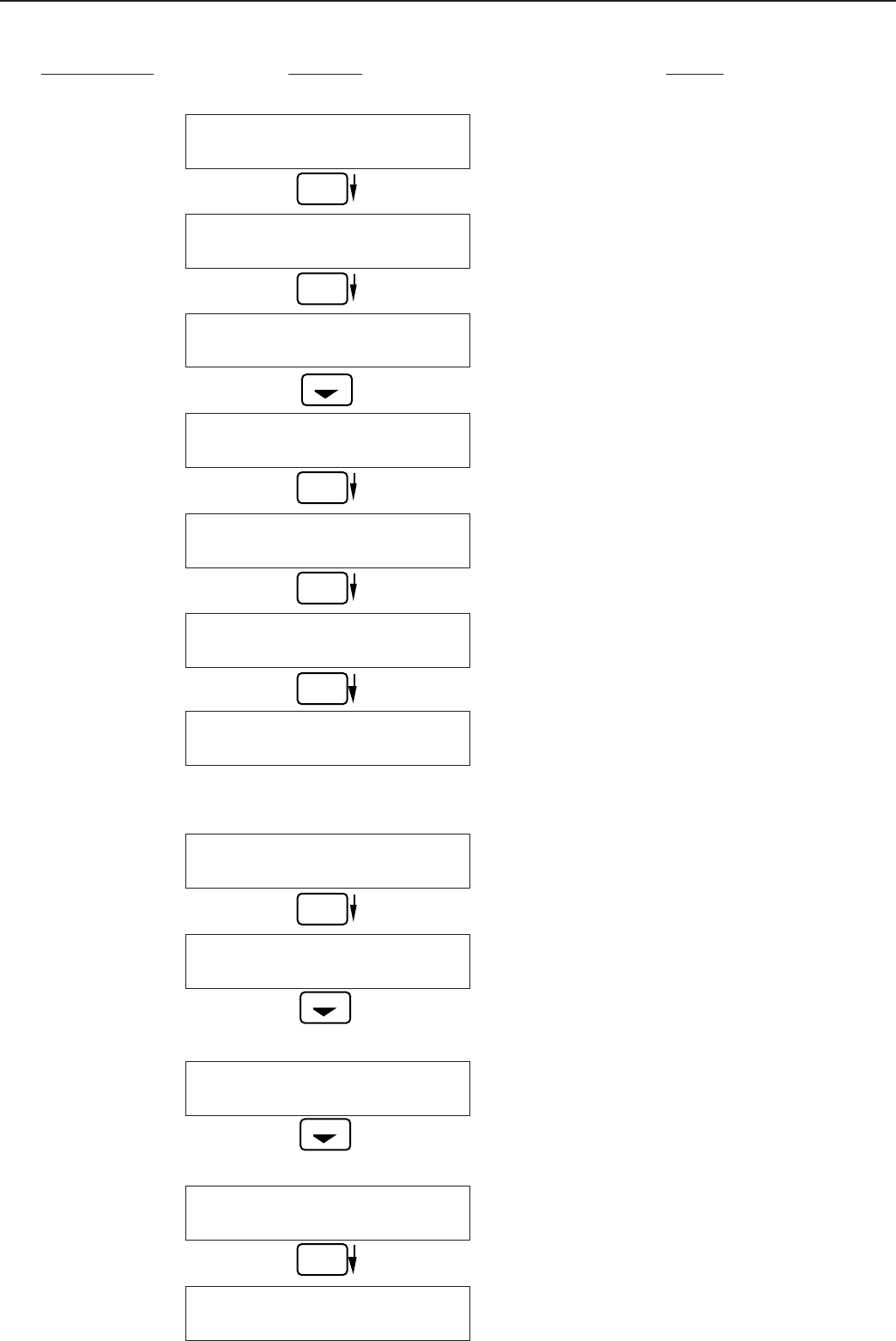
Calibrate 0mA out
+ TB1-15 - TB1-16
Calibrate 0mA out
Enter mA: 0.00000
Calibrate 0mA out
+ TB1-15 - TB1-16
Calibrate 20mA out
+ TB1-15 - TB1-16
Calibrate 20mA out
Enter mA: 20.00000
Calibrate 20mA out
+ TB1-15 - TB1-16
Calibrate
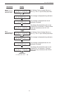
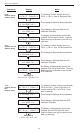
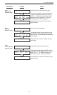
Analog In Test
Analog In Test Volts
T2:00.000 T5:00.000
Analog In Test mA
T3:00.000 T8:00.000
Analog In Test OHMS
RTD 00.000
Analog In Test
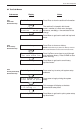
Connect ammeter to (+) TB1-15, (-) TB1-16.
Press enter.
To trim 0mA output: Press CLEAR to enable
editing and enter a small negative number (i.e. -
0.100) to force a display reading, then clear and
enter small quantity measured on your meter.
The display will return to Calibrate 0mA out.
Press the down arrow key to advance to Cal.
20mA out or repeat above if necessary.
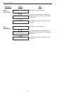
Connect ammeter to (+) TB1-15, (-) TB1-16.
Press enter.
To trim 20mA output: Press CLEAR to enable
editing and enter the current reading that is on
the ammeter display. Press enter.
The display will automatically return to the
Calibrate 20mA out submenu. Calibration is
complete.
Press the Menu key to go back to Calibrate
top-level menu.
Press enter to test the analog inputs.
To check voltage input accuracy: Use TB1-4
as Reference Ground, input 0-10 Volts to TB1-
2 and/or TB1-5. Display should show voltage
being input. Use voltage meter to verify input.
To check current input accuracy: Use TB1-4
as Reference Ground, input 0-20mA to TB1-3
and/or TB1-8. Display should show current
being input. Use ammeter to verify input.
To check RTD input accuracy: Connect a
jumper wire between TB1-6 and TB1-7, Place
a 100 ohm 0.1% resistor between TB1-7 and
TB1-8. Display should show 100 ohms ±0.1%.
Press Menu key to return to Analog In Test
top-level menu.
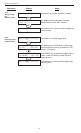
8.2.17
Analog In Test
Submenu Group