


31
FC-21 Flow Computer
ENTER
ENTER
ENTER
ENTER
ENTER
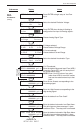
6.4.15 (Continued)
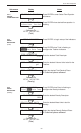
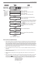
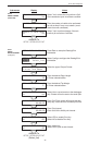
SETUP RELAYS
(Relay 3 & Relay 4)
ENTER
SETUP RELAYS
Rly1 Rly2 Rly3 Rly4
RELAY 3 USAGE
Rate Tot Aux Ovrn NA
RELAY 4 USAGE
Rate Tot Aux Alrm NA
RELAY 3 DELAY sec
0
RELAY 3 MODE
LO_ALARM HI_ALARM
RELAY 3 DURATION
#####
RELAY 3 SETPOINT
####### gal
RELAY 3 HYSTERESIS
##### gal/m
Advance To
SETUP CONTROL INPUTS
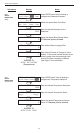
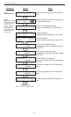
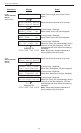
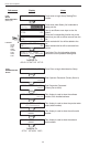
Select the desired Relay for setup.
(Relays 3 & 4 Optional)
If Relay 3 Selected,
Choose Rate, Total, Aux, Ovrn or NA.
If Relay 4 Selected,
Choose Rate, Total, Aux, Alrm or NA.
If Rate / Aux selected, enter desired relay
activation delay value.
Select the desired Relay Activation for Rate/Aux.
Low: Relay activates when reading is below
setpoint.
High:Relay activates when reading is above
setpoint.
If Total Selected, Enter desired Relay
Duration.
Enter the desired Setpoint.
If Rate, selected, Enter desired Relay
Hysteresis.
NOTE:
Settings for Relays
3 & 4 may be
entered even if
relays are not
supplied. The
settings will still
trigger display
alarms.
Sub-menus Display Notes
ENTER
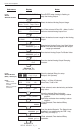
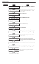
RELAY NOTES & CONSIDERATIONS
1. Relay activation is based on the computed readings not the displayed value. Therefore the display damping
factor will not affect the relay response time. The RELAY N DELAY feature allows the user to enter a time
delay for relay activation. This feature is very useful in applications where short over/under range conditions
are not considered alarm conditions. The Relay is a delay on make and delay on break. Alarm condition must
be continuously present for a time greater than the entered RELAY N DELAY in order for alarm to activate.
Once alarmed, the alarm condition must be continuously absent for a time greater than the entered RELAY N
DELAY in order for the alarm condition to be reset.
2. When INSTRUMENT TYPE is set to batcher, Relay 1 is reserved for PRESET and Relay 2 is reserved for
PREWARN.
3. Setting the relays to NA (Not Assigned), will allow the relay activation to be controlled via the RS-232 Serial
and/or RS-485 Modbus ports.
4. Relay 3 and Relay 4 settings may be used to trigger display alarm conditions even if the relays are not
supplied.
5. Relay 4 Alarm Operation. When Relay 4 is set for Alarm (Alrm) the relay functions as follows: The relay will
energize when it is NOT in an alarm condition. It is therefore recommended to use the Normally Closed
(N.C.) relay contacts on Relay 4 when wiring for alarm conditions. The Alarm Relay functions in this manner
to ensure that the alarm output will signal on power loss or blown fuse. Other alarm conditions include:
PULSEOUT OVERFLOW
SOFTWARE ERROR RESET
EXTENDED PFI LOCKUP
RTD/ THERM FAILURE