


6
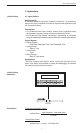
FC-21 Flow Computer
FC-21
FC-21
Bezel Adaptor
Gasket
Mounting Bracket
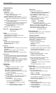
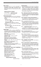
2. Installation
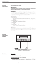
2.1 General Mounting Hints:
The FC-21 Flow Computer should be located in an area with a clean, dry
atmosphere which is relatively free of shock and vibration. The unit is
installed in a 5.43" (138mm) wide by 2.68" (68mm) high panel cutout.
(see Mounting Dimensions) To mount the Flow Computer, proceed as
follows:
a. Prepare the panel opening.
b. Slide the unit through the panel cutout until the it touches the panel.
c. Install the screws (provided) in the mounting bracket and slip the
bracket over the rear of the case until it snaps in place.
d. Tighten the screws firmly to attach the bezel to the panel. 3 in. lb. of
torque must be applied and the bezel must be parallel to the panel.
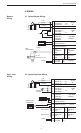
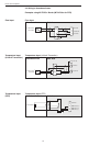
Termination Connectors:
Minimum Wire Gauge: 22 AWG
Maximum Wire Gauge: 14 AWG
Voltage/current limits are limited by unit specifications.
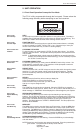
Permanently Connected Equipment:
UL 3101-1, Section 6.12.2.1 specifies that:
•A switch or circuit breaker shall be included in the building
installation;
• It shall be in close proximity to the equipment and within easy
reach of the OPERATOR;
• It shall be marked as the disconnecting device for the equipment.
Ensure that the switch or circuit breaker chosen is suitable for the
power requirements of the unit.
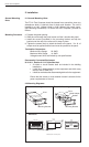
2.2 Mounting Diagrams:
General Mounting
Hints
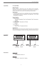
Mounting Procedure
Mounting Bracket
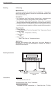
Standard Mounting Bezel Kit Mounting
Dimensions
Dotted Line Shows Optional Bezel Kit
Panel
Cutout
5.43
(138)
2.68
(68)
Dimensions are in inches (mm)
5.67 (144)
2.83
(72)
3.43
(87)
6.18
STOP
START
PRINT
5
0
–
TIME
CLEAR
•
MENU
ENTER
HELP
TEMP
4
PRE 1
3
RATE
2
TOTAL
1
GRAND
6
SCROLL
7
PRE 2
8
DENS
9
RATE
TOTAL
267395.749
GPM
GAL
147.43
6.15
(156)
0.5
(13)
0.28 (7.2)
0.4 (10)