


52
FC-21 Flow Computer
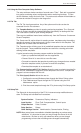
Sub-menus Display Notes
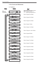
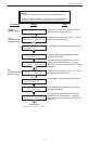
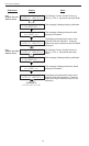
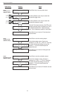
Pulse input test
Pulse input test
Trigger level 2.5V
Pulse input test
count speed 3kHz
Pulse input test
F1: 0 F2: 0
Pulse input test
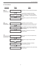
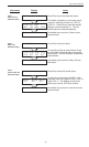
Analog out test
Analog out test
*0 4 10 15 20 mA
Analog out test
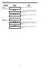
Excitation out test
Excitation out test
*5v 12v 24v
Excitation out test
Press Enter key to test the pulse input.
Use the Up/Down arrow keys to select the
appropriate trigger level.
Use the Up/Down arrow keys to select the
appropriate frequency range.
To check Pulse input accuracy: Use TB1-4 as
reference ground, input a frequency on TB1-2.
The display should show frequency being
input. Use a frequency counter to verify input.
Press Menu key to return to Pulse input test
top-level menu.
Press Enter to test the analog output.
To simulate analog output: Connect an
ammeter to (+) TB1-15, (-) TB1-16. Press the
key under the desired setting to move the
asterisk (*). The unit should output the
selected current.
Press Menu key to return to Analog out test
top-level menu.
Press Enter to test the excitation output.
To test the excitation output: Connect a
voltmeter to (+) TB1-1, (-) TB1-4. Press the
key under the desired setting to move the
asterisk (*). The unit should output the
selected voltage.
Press Menu key to return to Excitation out test
top-level menu.
8.2.18
Pulse input test
Submenu Group
ENTER
ENTER
ENTER
MENU
ENTER
MENU
8.2.19
Analog out test
Submenu Group
8.2.20
Excitation out test
Submenu Group
ENTER
MENU
STOP
START
STOP
START
2.5V
10mV
100mV
40Hz
3KHz
20kHz