


43
FC-21 Flow Computer
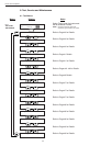
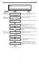
7.6 Linearization Table
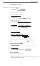
7.6.1 Linearization Table General Information
The Linearization Table is used when the flow input device gives a nonlinear
input signal. The unit uses up to 16 different points, as entered by the
operator, to form a curve for linearizing the input signal.
Notes:
1) A minimum of three points must be set up.
2) If "0" is entered for the frequency of any point other than point 1, the Flow
Computer assumes there are no more points above the points that preceded
them. The display will advance to the next setup prompt. Extrapolation is
taken from the last two nonzero points.
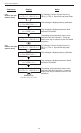
3) If the input frequency is above the highest or below the lowest frequency
programmed, the unit will use the last known point for the K factor in
computing the resulting actual flow.
4) Frequencies or apparent flows should be entered in ascending order.
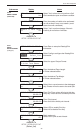
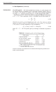
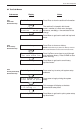
7.6.2 Linearization Table for Pulse Inputs
The linearization table for pulse inputs programming is quite simple when
values of frequency and flow are known. The Flow Computer asks for 16
different frequencies (Freq) and 16 corresponding K factors (K). It then uses
this data to determine what the actual flow is for any given input frequency.
Usually the necessary data is provided with the flowmeter.
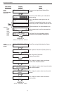
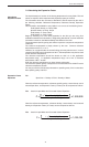
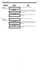
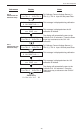
7.6.3 Linearization Table for Analog Inputs
The Linearization Table for Analog inputs programming is similar to the Pulse
input setup. The Flow Computer asks for 16 different flow rates (apparent
flow) and 16 corresponding Correction Factors. It then uses this data to
determine what the Actual flow is for any given apparent input signal. Again, a
minimum of three points must be set up.
Correction factor =
Actual Flow
Apparent Input Flow
The same rules that applied for the Digital setup apply for the Analog setup as
well.
The Flow Computer prompts you for the Apparent input signal (APR) and a
correction factor CFr) to multiply it by to yield true actual flow.
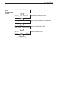
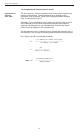
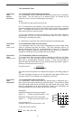
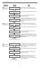
7.6.4 Linearization Table Interpolation
The Linearization Table routine uses the entered data to determine the K
factor for any given input frequency or input flow signal. This is done by taking
the closest data points above and below the input signal, then using those
points to extrapolate the K factor (correction factor), then calculating the
uncompensated flow from the data. Below are the formulas.
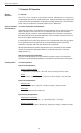
Parameters:
Determine closest point above input signal
signal = X, K factor (correction factor) = KA
Determine closest point below input signal
signal = Y, K factor (correction factor) = KB
Let input signal = H,
unknown K factor (correction factor) = KN
To find KN use this formula:
KA
KN
KB
Y H
X
Input
K factor
x (KA - KB) + KB = KN
H - Y
X - Y
Linearization
Table
General
Information
Linearization
Table
(Pulse Inputs)
Linearization
Table
(Analog Inputs)
Linearization
Table
Interpolation