


17
FC-21 Flow Computer
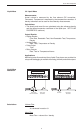
Slow Start Quantity
The Slow Start Quantity is a function that allows an amount to be entered for a
Slow Start up. This function requires two stage valve control. RLY 1 (slow flow)
will energize for Slow Start and RLY 2 (fast flow) will energize after the Slow
Start Quantity has been delivered. This helps reduce turbulence when filling an
empty container.
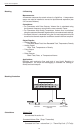
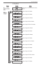
START, RESET/START and STOP, STOP/RESET
When configuring the control inputs, Control Input1 can be set for START or
RESET/START. When set for START, the unit will start batching when a signal
is applied to Control Input1 or the front panel Start key is pressed. A separate
Reset signal must be used to clear the previous batch total. When set for
RESET/START, the unit will automatically reset then start when a signal is
applied to Control Input1 or the front panel Start key is pressed (provided that
the pervious batch was completed). If a previous batch was stopped during a
batch cycle, the unit will Start from where it was stopped.
Control Input 2 can be set for STOP or STOP/RESET. When set for STOP, the
unit will stop batching when a signal is applied to Control Input 2 or the front
panel Stop key is pressed. A separate Reset signal must be used to clear the
batch total. When set for STOP/RESET, a running batch will stop when a
signal is applied to Control Input 2 or the front panel Stop key is pressed. If the
unit is Stopped or after a completed batch, the unit will reset when a signal is
applied to Control Input 2 or the front panel Stop key is pressed.
NOTE: Applying a voltage level to Control Input 2 will inhibit all Start inputs in
either mode.
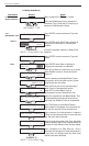
5.4.2 Password Protection for Batcher Mode
After an Operator and/or Supervisor Password is entered in the setup mode
(see section 6.3, SETUP PASSWORD submenu), the unit will be locked. The
unit will prompt the user for the password when trying to perform the following
functions:
Clear Grand Total
Enter Menu
The Supervisor password should be reserved for supervisors. The Supervisor
password will allow access to restricted areas of the Setup and Test menus.
The passwords are factory set as follows:
Operator = 0
Supervisor = 2000
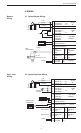
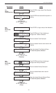
5.4.3 Relay Operation in Batcher mode
Up to four relays are available (two standard) for alarm outputs. Preset 1
(RLY1) is reserved for batch amount, Preset 2 (RLY2) is reserved for prewarn.
(see section 5.4 Batcher Operation for Relay 1 & Relay 2 functions)
Preset 1 (RLY1) and Preset 2 (RLY2) are easily accessible by pressing the PRE
1 or PRE 2 key on the front panel. Preset 3 and Preset 4 are accessible only
through the setup menu.
Relays 3 and 4 can be assigned to trip according to rate, total, temperature,
overrun or alarm. When Rate is selected the relays can be programmed for low
or high alarms.
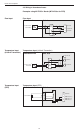
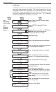
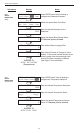
5.4.4 Pulse Output in Batcher mode
The isolated pulse output (open collector) is menu assignable to Volume Total,
Corrected Volume Total or Mass Total. The pulse output duration can be set for
10mS (50 Hz max) or 100mS (5 Hz max). A pulse output scale factor (pulse
value) can be set to scale the pulse output. The pulse output is ideal for
connecting to remote totalizers or other devices such as a PLC. See section 1.3
for electrical specifications.
5.4.5 Analog Output in Batcher mode
The analog output is menu assignable to correspond to the Volume Rate,
Corrected Volume Rate, Mass Rate, Temperature, Density, Volume Total,
Corrected Volume Total or Mass Total. The analog output is ideal for "trend"
tracking using strip chart recorders or other devices.
Password Protection
(Batch mode)
Relay Operation
(Batch mode)
Pulse Output
(Batch mode)
Analog Output
(Batch mode)