


Crankshaft, Cylinder Block, Flywheel and
6A1 ENGINE (E-W) -
Drive Plate
11A-15-3
9EN0477
6AE0108
Arrow
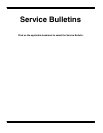
Shank length
90
è
- 100
è
Paint marks
Paint marks
6EN0955
6AE0109
+
B
G
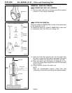
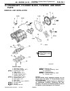
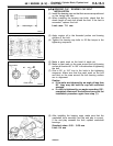
BEARING CAP / BEARING CAP BOLT
INSTALLATION
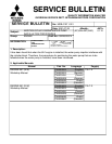
(1) Install the bearing caps so that their arrows are positioned
on the timing belt side.
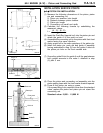
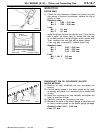
(2) When installing the bearing cap bolts, check that the
shank length of each bolt meets the limit. If the limit is
exceeded, replace the bolt.
Limit: max. 71.1 mm
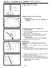
(3) Apply engine oil to the threaded portion and bearing
surface of the bolt.
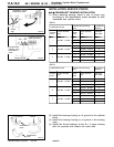
(4) Tighten the bearing cap bolts to 25 Nm torque in the
tightening sequence.
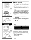
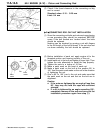
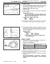
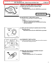
(5) Make a paint mark on the head of each nut.
(6) Make a paint mark on the area around the bolt bearing
surface at location 90è to 100è in the direction of tightening
the bolt.
(7) Give a 90è to 100è turn to the bolts in the tightening
sequence. Make sure that the paint mark on the bolt
and that on the area around the bolt bearing surface
are in alignment.
Caution
J
If the bolts are tightened by an angle of less than
90
è
, they may not hold the cap with sufficient
strength.
J
If a bolt is tightened by an angle exceeding 100
è
,
completely remove all the bolts and carry out the
installation procedure again from step (1).
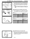
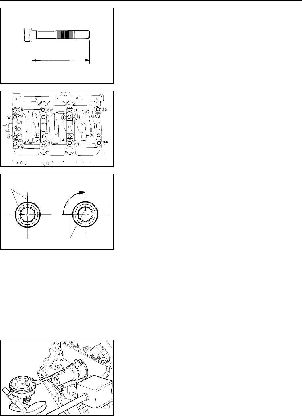
(8) After installing the bearing caps, make sure that the
crankshaft turns smoothly an d the end play is correct.
If the end play exceeds the limit, replace crankshaft
bearings.
Standard value: 0.05 - 0.25 mm
Limit: 0.4 mm
K
Mitsubishi Motors Corporation Feb. 1997 PWEE9622