


11A-14-2
6A1 ENGINE (E-W) -
Piston and Connecting Rod
REMOVAL SERVICE POINTS
G
A
+
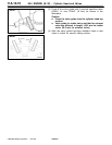
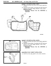
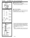
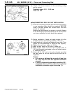
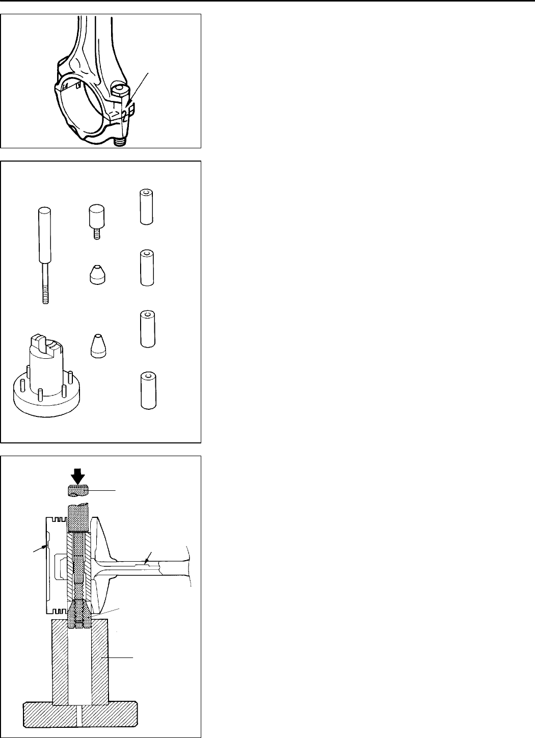
CONNECTING ROD CAP REMOVAL
(1) Mark the large end of the connecting rod with the cylinder
Cylinder No.
number for use during reassembly.
DEN0050
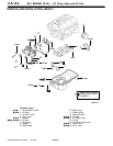
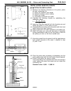
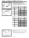
Piston pin setting tool MD998780
Push rod
Guide A:
17.9 mm
Guide B
Guide A:
18.9 mm
Guide C
Guide A:
20.9 mm
Guide D
MB991659
Guide A:
21.9 mm
Base
9EN0780
Front
mark
Base
Push rod
Front mark
Guide D
7EN0390
G
B
+
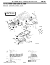
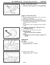
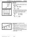
PISTON PIN REMOVAL
Piston pin setting tool (MD998780) consists of the parts shown
in the illustration at left.
To remove the piston pin, Guide D (MB991659) is also used
in combination with the Piston pin setting tool.
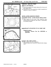
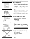
(1) Insert the Push Rod (special tool) into the piston from
the side on which the front mark is stamped in the piston
head, and attach the guide D to the push rod end.
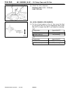
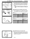
(2) Place the piston and connecting rod assembly on th e
Piston Pin Setting Base (special tool) with the front mark
facing upward.
(3) Using a press, remove the piston pin.
NOTE
Keep the disassembled pistons, piston pins and
connecting rods in order according to the cylinder number.
K
Mitsubishi Motors Corporation Feb. 1997 PWEE9622