


11A-14-4
6A1 ENGINE (E-W) -
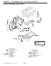
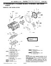
Piston and Connecting Rod
6AE0194
1EN0269
7EN0452
9EN0524
No.1
No.2
Side rail gap
Piston ring expander
Size mark
Identification mark
Identification mark
Upper
ring
Lower
in
side rail
No. 1
gap
side rail
Piston p
No. 2
and spacer gap
6EN0549
K
Mitsubishi Motors Corporation Feb. 1997
+
B
G
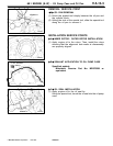
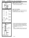
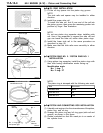
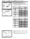
OIL RING INSTALLATION
(1) Fit the oil ring spacer into the piston ring groove.
NOTE
The side rails and spacer may be installed in either
direction.
(2) Install the upper side rail.
To install the side rail, first fit one end of the rail into
the piston groove, then press the remaining portion into
position by finger. See illustration.
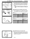
NOTE
Do not use piston ring expander when installing side
rail. Use of ring expander to expand the side rail end
gap can break the side rail, unlike other piston rings.
(3) Install the lower side rail in the same procedure as
described in step (2).
(4) Make sure that the side rails move smoothly in either
direction.
+
C
G
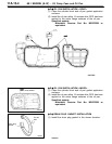
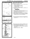
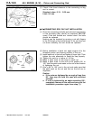
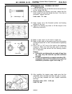
PISTON RING NO. 2 / PISTON RING NO. 1
INSTALLATION
(1) Using piston ring expander, install the piston rings with
their side having identification marks facing up.
Identification mark:
No. 1 ring: T
No. 2 ring: 2T
NOTE
The piston ring is stamped with the following size mark.
Size Size mark
Standard size None
0.50 mm O.S. 50
1.00 mm O.S. 100
+
D
G
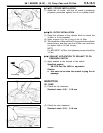
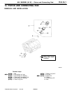
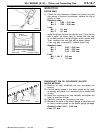
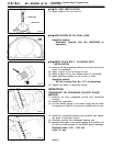
PISTON AND CONNECTING ROD INSTALLATION
(1) Liberally coat engine oil on the circumference of the piston,
piston ring, and oil ring.
(2) Arrange the piston ring and oil ring gaps (side rail and
spacer) as shown in the figure.
(3) Rotate crankshaft so that the crank pin is on center of
the cylinder bore.
PWEE9622