


6A1 ENGINE (E-W) -
Oil Pump Case and Oil Pan
11A-13-1
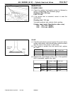
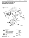
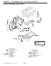
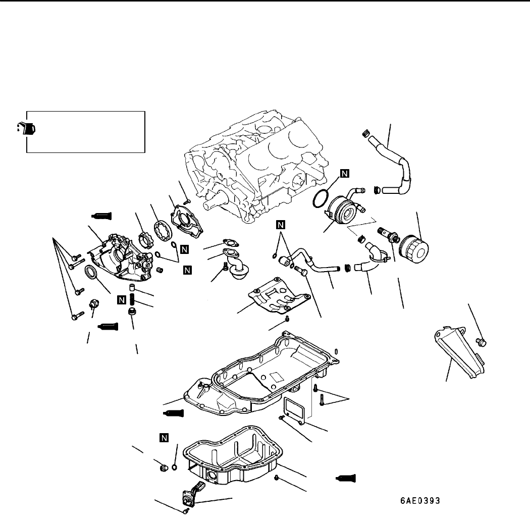
13. OIL PUMP CASE AND OIL PAN
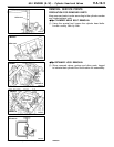
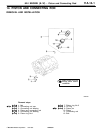
REMOVAL AND INSTALLATION <SOHC>
installation.
1
2
4
5
6
7
8
9
10
11
12
13
14
15
16
17
18
19
20
23
3
21
24
25
26
22
Apply engine oil to all
moving parts before
19 Nm
44 Nm
10 Nm
9Nm
7Nm
7Nm
7Nm
9Nm
39 Nm
21 Nm
68 Nm
14 Nm
12 Nm
30 Nm
Removal steps
+
I
G 1. Oil pressure switch
+
D
G 14. Oil pan upper
+
H
G 2. Oil filter
15. Buffle plate
3. Oil filter cover
16. Oil screen
4. Water hose (for Europe and GCC)
17. Gasket
5. Water pipe (for Europe and GCC)
18. Relief plug
6. Water pipe (for Europe and GCC)
19. Relief spring
7. Bolt (for Europe and GCC)
20. Relief plunger
+
G
G 8. Oil cooler (for Europe a nd GCC)
+
C
G 21. Oil seal
9. Drain plug
+
B
G 22. Oil pump case
+
F
G 10. Gasket
23. O-ring
11. Oil level sensor (For Europe)
24. Oil pump case cover
12. Cover
+
A
G 25. Outer rotor
+
D
G 13. Oil pan lower
+
A
G 26. Inner rotor
K
Mitsubishi Motors Corporation Feb. 1997 PWEE9622