


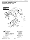
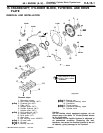
6A1 ENGINE (E-W) -
Piston and Connecting Rod
11A-14-3
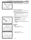
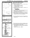
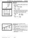
Piston
A
B
C
D
Connecting rod
Piston pin
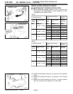
7EN0432
7EN0433
3mm+L
Guide B
Guide A
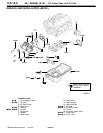
INSTALLATION SERVICE POINTS
+
A
G
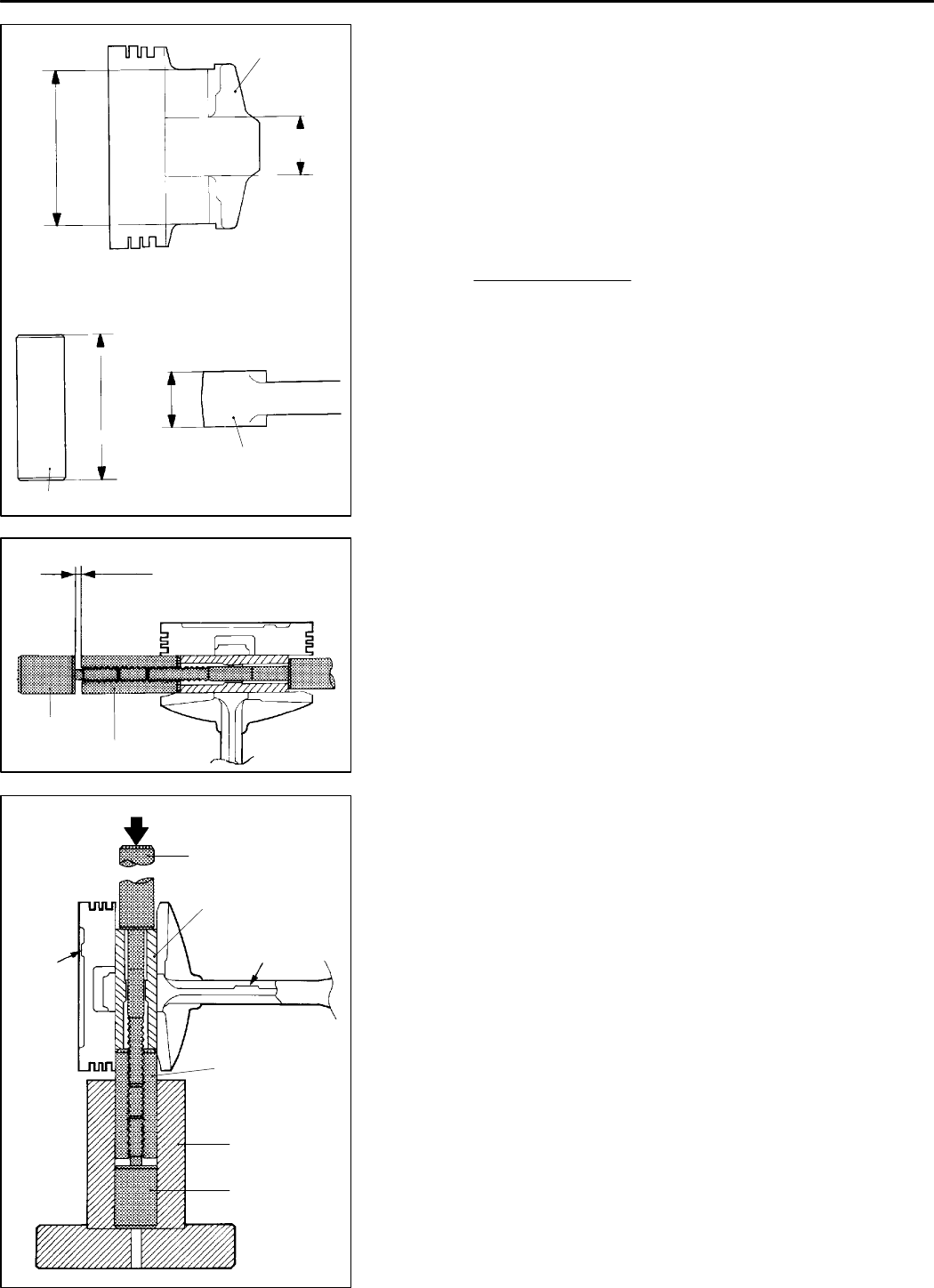
PISTON PIN INSTALLATION
(1) Measure the following dimensions of the piston, piston
pin and connecting rod.
A: Piston pin insertion hole length
B: Distance between piston bosses
C: Piston pin length
D: Connecting rod small end width
(2) Calculate the following formula by substituting the
measured values.
(A - C) - (B - D)
L=
2
(3) Insert the Push Rod (special tool) into the piston pin a nd
attach the guide A to the push rod end.
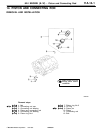
(4) Assemble the connecting rod in th e piston with their front
marks facing the same direction.
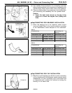
(5) Apply engine oil to the entire periphery of the piston pin.
(6) Insert the piston pin, push rod and guide A assembly
having assembled in step (3) from the guide A side into
the piston pin hole on the front marked side.
(7) Screw the guide B into the guide A until the gap between
both guides amounts to the value L obtained in step
(2) plus 3 mm.
Front
mark
Base
Push rod
Piston pin
Front mark
Guide A
Guide B
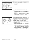
(8) Place the piston and connecting rod assembly onto the
piston setting base with the front marks directed upward.
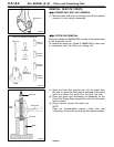
(9) Press-fit the piston pin using a press.
If the press-fitting force required is less than the standard
value, replace the piston and piston pin set or/and the
connecting rod.
Standard value: 5,000 - 15,000 N
7EN0391
K
Mitsubishi Motors Corporation Feb. 1997 PWEE9622