


11A-10-2
6A1 ENGINE (E-W) -
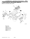
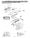
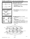
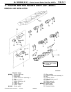
Rocker Cover and Camshaft <MIVEC>
Left bank
camshaft
Right bank
camshaft
6AE0229
6AE0230
Right
bank
in
Left
bank
in
EX
EXIN
IN
6AE0233
Dowel p
Dowel p
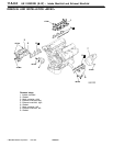
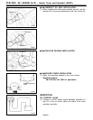
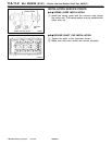
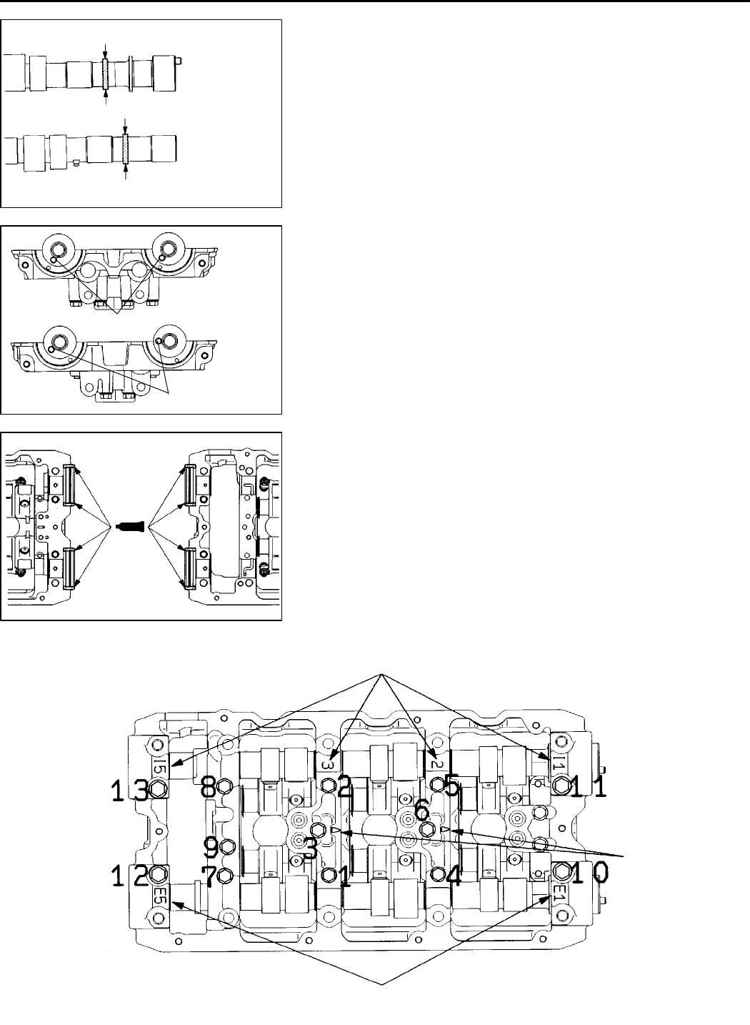
INSTALLATION SERVICE POINT
+
A
G
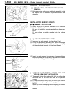
CAMSHAFT INSTALLATION
(1) Intake valve camshaft a n d exhaust valve camshaft can
be identified by their diameters at th e portions indicated
in t he illustration.
Intake valve camshaft: 25 mm
Exhaust valve camshaft: 30 mm
(2) Before installing each camshaft, apply engine oil to its
journals and cams.
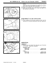
(3) The camshaft dowel pins must be positioned as shown
in the illustration.
+
B
G
/
camshaft
holders.
6AE0308
Intake
Exhaust
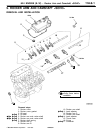
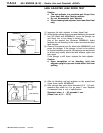
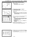
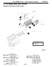
CAMSHAFT BEARING CAP CAM CAP
INSTALLATION
(1) Apply sealant to the illustrated points of th e
Specified sealant:
3M ATD part No. 8660 or equivalent
(2) Install th e bearing caps a n d cam caps correctly according
to the “I” (intake) and “E” (exhaust) marks as well as
the stamped cap numbers and front marks.
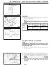
(3) Tighten the bolts in the sequence of the numbers shown
in the illustration.
Cap No.
Cap No.
Front mark
K
Mitsubishi Motors Corporation Feb. 1997 PWEE9622