


6A1 ENGINE (E-W) -
Piston and Connecting Rod
11A-14-5
6AE0097
in
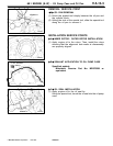
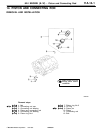
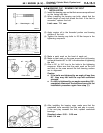
Check
digit
No.1
No.3
No.5
No.2
No.4
No.6
Crankshaft p
identification mark
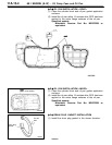
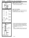
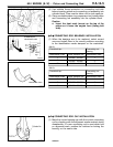
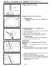
(4) Use suitable thread protectors on connecting rod bolts
before inserting piston and connecting rod assembly into
cylinder block. Care must be taken not to nick crank pin.
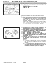
(5) Using a suitable piston ring compressor tool, install piston
and connecting rod assembly into the cylinder block.
Caution
J
Insert the front mark (arrow) on the top of the
piston so it faces the engine front (timing belt
side).
+
E
G
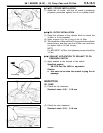
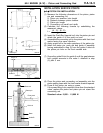
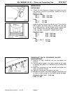
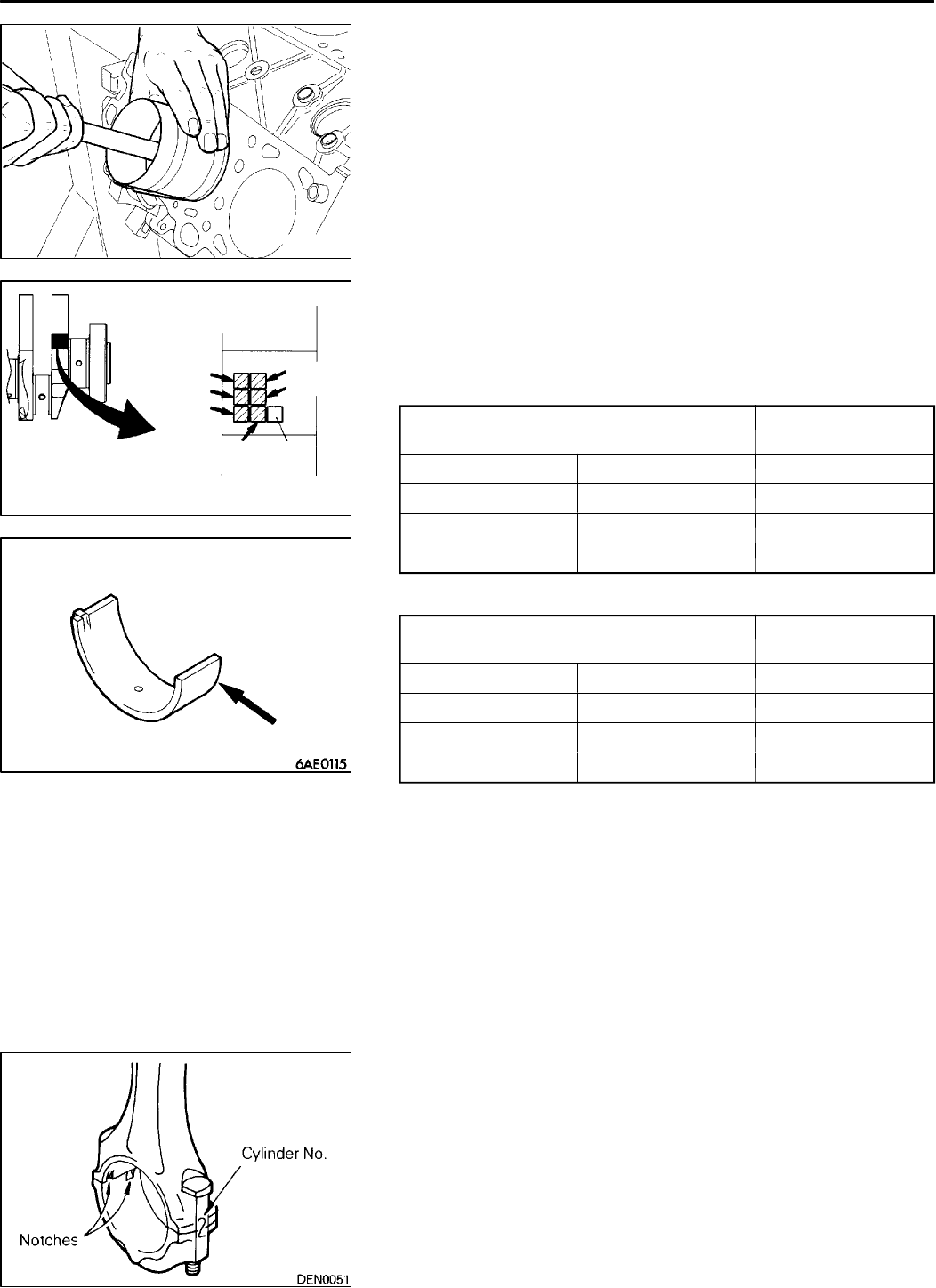
CONNECTING ROD BEARINGS INSTALLATION
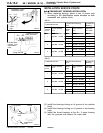
(1) When the bearings are to be replaced, select correct
ones and install them in the correct positions according
to the identification marks stamped on the crankshaft.
<6A12>
42.995 - 43.000
42.985 - 42.995
Crankshaft pin
Connecting rod
bearing
Identification mark Outer diameter mm Identification mark
I
1
6AE0341
II
2
III
42.980 - 42.985 3
<6A13>
Identification mark
bearing
I
50.995 - 51.000 1
II
50.985 - 50.995 2
III
50.980 - 50.985 3
Crankshaft pin
Connecting rod
Identification mark Outer diameter mm Identification mark
+
F
G
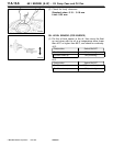
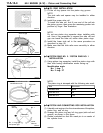
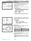
CONNECTING ROD CAP INSTALLATION
(1) Mate th e correct bearing cap with the correct connecting
rod by checking with the alignment marks marked during
disassembly. If a new connecting rod is used which has
no alignment mark, position the notches for locking the
bearing on the same side.
K
Mitsubishi Motors Corporation Feb. 1997 PWEE9622