


12-20 FIN AL DRIVE
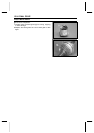
Output Bevel Gears
•
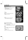
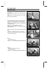
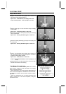
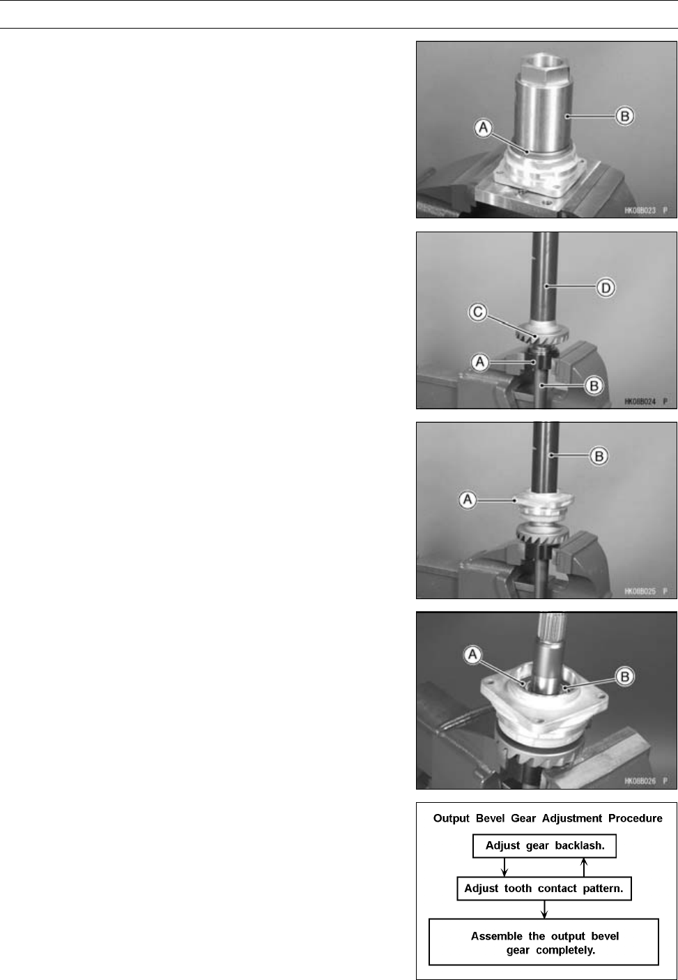
Apply a non-permanent locking agent to the threads of
the bearing holder [A] and tighten it.
Special Tool - Socket Wrench, Hex 50 [B]: 57001-1478
Torque - Bearing Holder: 137 N·m (14 kgf·m, 101 ft·lb)
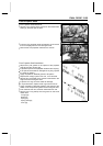
•
Hold the holder [A] in a vise, and set the output shaft [B]
on the holder.
Special Tool - Output Shaft Holder: 57001-1570
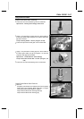
•
Press the output driven bevel gear [C] using the driver [D]
until it is bottomed.
Special Tool - Steering Stem Bearing D river: 57001-137
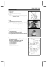
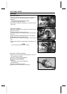
•
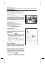
Press the housing assembly [A] using the driver [B] until
it is bottomed.
Special Tool - Steering Stem Bearing D river: 57001-137
•
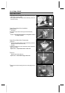
Apply a non-permanent locking agent to the threads of
the output shaft holder nut [A] and tighten it so that the
projection side [B] faces outward.
Special Tool - Socket Wrench: 57001-1482
Torque - Output Shaft Holder Nut: 157 N·m (16 kgf·m, 116
ft·lb)
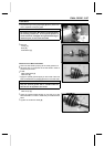
•
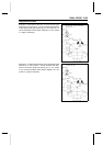
Apply grease to the oil seal and press it so that it is flush
with the end surface of the housing.
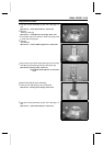
Output Bevel Gears Adjustment
The backlash and tooth contact pattern of the bevel
gears must be correct to prevent the gears from making
noise and being damaged.
When replacing any one of the backlash-related parts, be
sure to check and adjust the backlash and tooth contact.
First adjust the backlash, and then tooth contact by replac-
ing shims.
These two adjustments are of critical importance and
must be carried out in the correct sequence, using the
procedures shown.