


GNS 530(A) Pilot’s Guide and Reference
190-00181-00 Rev. H
SECTION 6
PROCEDURES
6-18
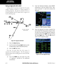
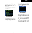
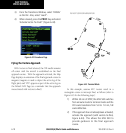
3) From the Transitions Window, select ‘D258G’
as the IAF. Also, select ‘Load?’.
4) When cleared, press the PROC Key and select
‘Activate Vector-To-Final?’ (Figure 6-42).
Figure 6-42 Procedures Page
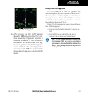
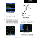
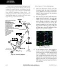
Flying the Vectors Approach
With ‘vectors to nal’ selected, the CDI needle remains
off center until the aircraft is established on the final
approach course. With the approach activated, the Map
Page displays an extension of the nal approach course in
magenta (magenta is used to depict the active leg of the
ight plan) and ‘VTF’ appears as part of the active leg on
the Default NAV Page (as a reminder that the approach
was activated with vectors-to-nal).
DO NOT USE FOR NAVIGATION
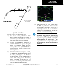
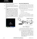
Figure 6-43 Terminal Mode
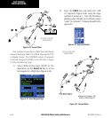
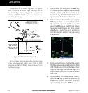
In this example, assume ATC vectors result in a
rectangular course to intercept nal, as follows (refer to
Figure 6-43 for the following steps):
1) Within 30 nm of KTOP, the GNS 530 switches
from enroute mode to terminal mode and the
CDI scale transitions from 5.0 to 1.0 nm, full
scale deflection.
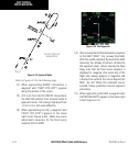
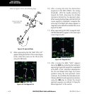
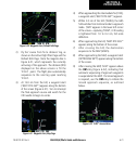
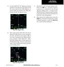
2) If the approach has not already been activated,
activate the approach (with vectors-to-final,
Figure 6-44). This allows the GNS 530 to
provide guidance to the final approach
course.