


3-1
3. RADAR OPERATION
This chapter covers radar operation, including the ARP (Auto Plotter) function.
ARP requires a Model 1800/1900 series network radar equipped with the ARP
circuit board.
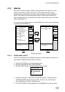
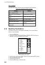
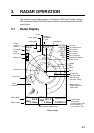
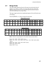
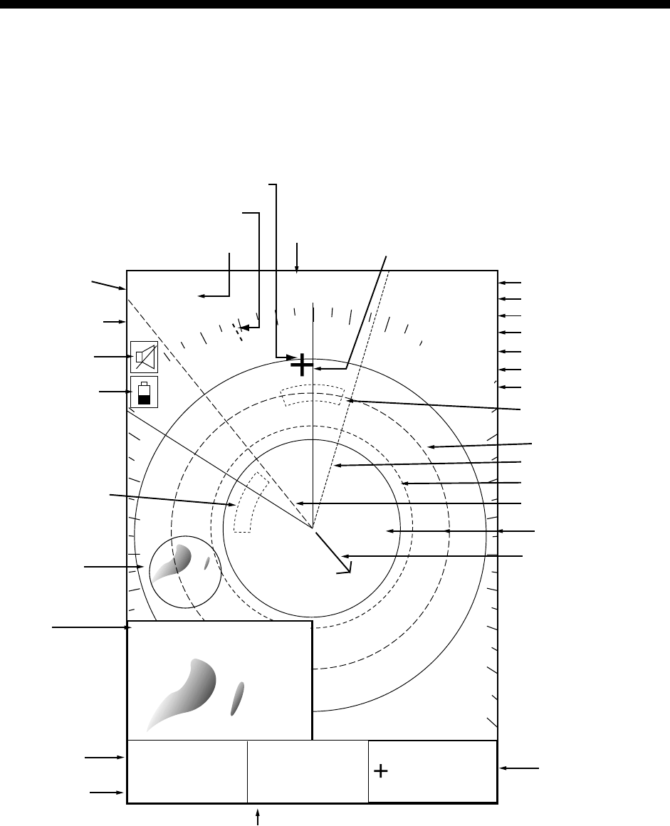
3.1 Radar Display
Cursor
359.9°R
0.240nm
North marker
H-UP
. / 319.9
°M
.125nm
SP
TRAIL 30m
02m30s
G1 IN
G2 OUT
ES L
EAV L
IR L
.250
Range/
range ring
interval
Presentation
mode
Alarm icon
Battery icon
Zoom area
Zoom
window
Guard zone 1
Trail time
Trail elapsed time
Guard zone 1
Guard zone 2
Echo stretch
Echo averaging*
Interference rejector
Guard zone 2
VRM2
EBL1
VRM1
EBL2
Range ring
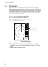
Pulselength
Heading
M: Magnetic
T: True
Heading line
EBL1 range
VRM1 range
Cursor range
and bearing
(Cursor position may
also be shown, in
L/L or Loran C TD.)
EBL2 bearing, VRM2 range
EBL1
27.0°R
VRM1
0 .158nm
EBL2
327.1°R
VRM2
0 .225nm
* = Radar source
Model 1800/1900
series radar
Own ship vector
(ARP required*,
true vector mode)
Radar display