


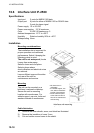
10. INSTALLATION
10-20
Grounding
To prevent electrical shock and mutual interference, run a ground wire between
the earth terminal on the unit and ship’s superstructure.
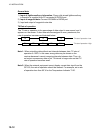
Cabling schedules
The signal cable should be a twisted-pair, double-screened cable. Ground the
signal cable at the cable clamp.
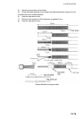
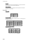
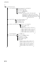
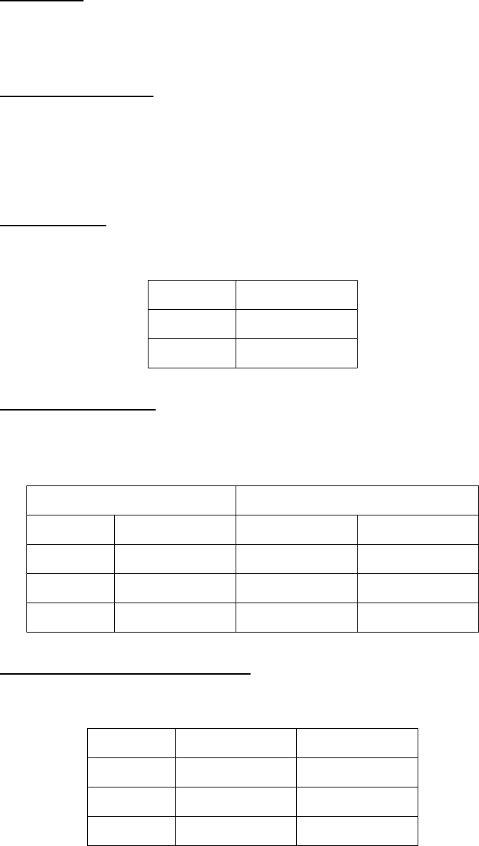
Connections
Power supply
J1 (24 VDC)
Pin no. Designation
#1 +
#2 -
Input signal (NMEA)
The signal from GPS navigator is connected to J2 and J3. Data being fed to J2
has higher priority than J3.
J2 J3
Pin no. Designation Pin no. Designation
#3 RD1-H #3 RD2-H
#4 RD1-C #4 RD2-C
#6 GND #6 GND
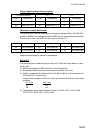
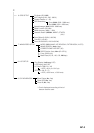
Output signal (RS-422 or NMEA)
J4, J5, J6, J7, J8, J9
Pin no. RS-422 NMEA
#1 TD-B TD-H
#2 TD-A TD-C
#4* GND GND
*#5 for J9