


APPENDIX
AP-8
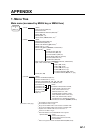
2. Digital Interface
Input sentences (RP Board, J4)
BWC*, BWR*, DBS, DBT, DPT, DTM, GGA, GLC, GLL, HDT, MTW, MWV, RMA, RMB,
RMC, RTE VBW, VDR, VHW, VTG, VWR, VWT, WPL, ZDA, !AIVDM, !AIVDO, $AIALR
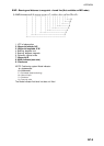
Output sentences
OSD, TLL*, TTM, RSD
*: Not available on IMO radar
Data reception
Data is received in serial asynchronous form in accordance with the standard referenced in
IEC 61162-2.
The following parameters are used:
Baud rate: 38,400 bps: HDT, !AIVDM, !AIVDO and $AIALR. All other sentences: 4800 bps
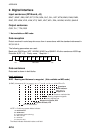
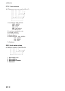
Data bits: 8 (D7 = 0), Parity: none, Stop bits: 1
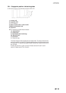
D0 D1 D2 D3 D4 D5 D6 D7
Start
bit
Stop
bit
Data bits
Data sentences
Data used is shown in bold italics.
Input sentences
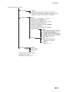
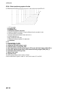
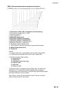
BWC - Bearing and distance to waypoint (Not available on IMO radar)
$--BWC, hhmmss.ss, llll.ll, a yyyyy.yy, a, x.x, T, x.x, M, x.x, N, c--c, a*hh<CR><LF>
Checksum
Mode indicator
(see note 1)
Waypoint ID
Distance, nautical miles
Bearing, degrees true
Waypoint longitude, E/W
Bearing, degrees magnetic
Waypoint latitude, N/S
UTC of observation*
NOTE 1: Positioning system Mode indicator:
A = Autonomous
D = Differential
E = Estimated (dead reckoning)
M = Manual input
S = Simulator
N = Data not valid
The Mode indicator field shall not be a null field.