


1. RADAR OPERATION
1-84
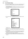
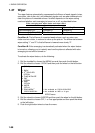
[ANT INFORMATION]
ANT NO 1
BAND : X-BAND
MODEL : 12 UP
POS : FORE
ANT NO 2
BAND : X-BAND
MODEL : 25 UP
POS : MAIN TOP
ANT NO 3
BAND : S-BAND
MODEL : 30 UP
POS : MAIN 2ND
ANT NO 4
BAND :
MODEL :
POS :
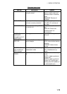
OWN RADAR NO.
8 SUB MONITOR*
OFF/ON
9 INTER SW PRIORITY
OFF/ON
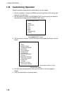
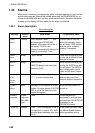
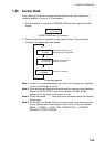
1.44.2 Displaying antenna information
The antenna information display shows data (radar band, model and position) on
the radar antennas currently powered. If an antenna is not powered, its data
area is blank.
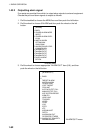
1. Roll the trackball to place the arrow in the ANTENNA box at the left side of
the screen.
2. Push the left button to choose the antenna for which you want to find
information. (You cannot choose an antenna which does not exist or one
which is not powered.)
3. Push the right button to show the antenna information display.
* Not available on IMO or A type
ANTENNA INFORMATION display
4. Push the right button to close the antenna information display.
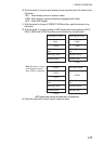
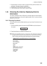
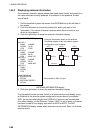
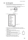
The interswitch function permits control of all antennas from any display, using
an Ethernet In the antenna system configuration shown above, for example,
ANT1 can be controlled directly from DISPLAY-A, and also can be controlled
from other displays, via the Ethernet. Further, if ANT1 is out of order or its power
has been turned off, any display can switch to ANT2 or ANT3. The ANT
INFORMATION display shows which antennas can be used. Refer to it to know
antenna status.
Using the information shown on the antenna
information display at left, the antenna system
configuration looks as below.
ANT1 ANT2 ANT3
DISP-A DISP-B DISP-C
Ethernet
HUB