


4. AIS OPERATION
4-16
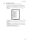
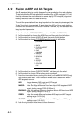
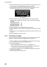
[FUSION]
1 BACK
2 FUSION TARGET
OFF/ON
3 GAP
0.000NM
4 RANGE
0.000NM
5 BEARING
00.0°
6 SPEED
0.0KT
7 COURSE
0.0°
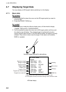
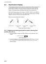
4.12 Fusion of ARP and AIS Targets
An AIS-equipped ship is usually displayed by two symbols on the radar display.
This is because the AIS ship position is measured by a GPS navigator (L/L) on
that ship whereas the radar detects the same ship by PPI principle (range and
bearing relative to own ship radar antenna).
To avoid the presentation of two target symbols for the same physical target, the
“fusion” function is incorporated. If target data from AIS and from radar plotting
functions are available and if the fusion criteria is fulfilled, only the activated AIS
target symbol is presented.
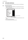
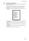
1. Confirm that the ARP ACQ MODE box shows AUTO or AUTO MANU.
2. Roll the trackball to choose the MENU box and then push the left button.
3. Roll the wheel to choose 4 ARP•AIS and then push the left button.
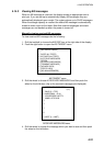
4. Roll the wheel to choose 7 [FUSION] and then push the left button.
FUSION menu
5. Roll the wheel to choose FUSION TARGET and then push the wheel.
6. Roll the wheel to choose ON and then push the wheel.
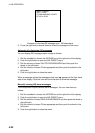
7. Enter the information below, pushing the wheel (or the [MARK ENTER] key)
after entering each data. This information will be used to determine which
ARP targets to convert.
GAP: Range between AIS target and ARP target.
(setting range: 0.000-0.999(nm))
RANGE: Enter the range difference from own ship to AIS target and ARP
target. (setting range: 0.000-0.999(nm))
BEARING: Enter the bearing difference from own ship to AIS target and ARP
target. (setting range: 0.0-9.9(°))
SPEED: Enter the speed difference between AIS target and ARP target.
(setting range: 0.0-9.9(kt))
COURSE: Enter the course difference between AIS target and ARP target.
(setting range: 0.0-9.9(°))
8. Push the right button three times to close the menu.