


©2011 Edelbrock LLC
Part #1596, 1597, 1598 & 1599
Brochure #63-1598
Rev. 2/11 - AJ/mc
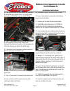
Edelbrock E-Force Supercharger System for
the 2010 Camaro SS
Installation Instructions
Page 17
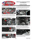
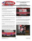
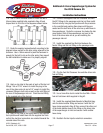
116. Use a 10mm universal socket to install the M6 x
45mm intake manifold bolts supplied in Bag #3 and
torque them to 89 in/lbs in the sequence shown below.
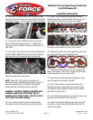
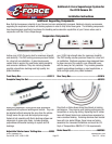
117. Route the supplied serpentine belt according to the
diagram below, except for the idler pulley adjacent to the
tensioner. Use a 16mm wrench to push the tensioner in
enough for the belt to slip on the idler pulley then inspect
the belt installation to make sure it is properly aligned.
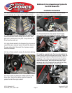
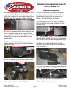
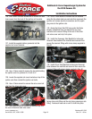
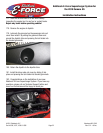
118. Apply o-ring lube to the seals of each of the fuel rail
fittings. Use a 13/16” wrench to install the plug in the
rear of the driver side rail and a 3/4” wrench to install the
crossover fittings in both rails as well as the inlet fitting at
the rear of the passenger side rail. Clock the inlet fitting
to the rounded side of the fuel rail.
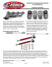
119. Apply o-ring lube to the upper seals of the supplied
fuel injectors and install them into the supplied fuel rails
so that the electrical connectors are oriented towards the
rounded side of the rails.
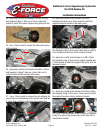
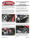
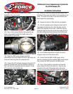
120. Connect the supplied Fuel Rail Crossover line with
the 90° fittings to the passenger side fuel rail then install
the fuel rails by lining up the injectors with the provisions
in the manifold and pushing them down until they are
seated and the bolt holes in the rails line up with those in
the supercharger. Route the crossover line below the hub
snout and air inlet of the supercharger and over to the
front of the driver side rail as you are installing the
passenger side rail.
121. Install the supplied Fuel Rail Inlet between the
fender fitting and fuel rail fitting on the passenger side.
122. Clip the Fuel Rail Crossover line onto the driver side
fuel rail fitting.
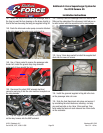
123. Use a 5mm Allen tool to install the four M6 x 12mm
fuel rail hold down bolts supplied in Bag #3.
124. Install the supplied Brake Booster to Manifold Hose
onto the brake booster fitting and secure it with the 3/4”
hose clamp supplied in Bag #2 then connect the other end
of the brake booster hose to the fitting on the driver side
of the supercharger air inlet and secure it with another
hose clamp.
125. Reattach the fuel injector electrical connectors.