


64
7.2 UBX Binary Protocol
To obtain the maximum performance from GPS chips, which mainly consists of
FV-25, u-blox proposed a proprietary binary protocol. The binary protocol can set and
poll all the available actions and messages from the module. Using asynchronous
RS232 ports, the module communicates with a host platform in terms of the
alternative, UBX protocol, to carry GPS data. The noticeable features for the UBX
protocol are
1. 8 bits binary data;
2. low-overhead checksum algorithm;
3. 2-stage message identifier, i.e., Class ID + Message ID.
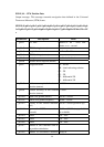
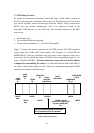
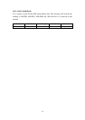
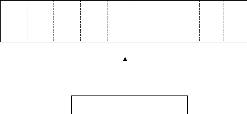
Figure 7.1 depicts the sentence structure for the UBX protocol. The UBX messages
always begin with “0xB5 0x62” (hex number). The selection of a CLASS ID and
MESSAGE ID, which are described in the end of this section, depends on the user’s
need, and it will also define the content of DATA and its corresponding length (i.e. the
value of DATA LENGTH). For those multi-byte values, the rule of little Endian
is adopted for transmitting the values. It is noticeable that the DATA LENGTH is
the value to indicate the length that only contains the subsequent input/output DATA
and doesn’t include the checksum bytes.
SYNC
CHAR
# 1
SYNC
CHAR
# 2
CLASS
ID
MESSAGE
ID
DATA
LENGTH
Little Endian
DATA
Little Endian
CHECKSUM
CK_A
CHECKSUM
CK_B
1 BYTE
0xB5
1 BYTE
0x62
1 BYTE
1 BYTE
2 BYTES
VARIED, depends
on the size of content of the
“CLASS + MESSAGE”
ID
1 BYTE
1 BYTE
indicates the following length for data which
doesn’t include the 2 bytes for checksum.
Figure 7.1 UBX protocol structure.
SYNC
CHAR
# 1
SYNC
CHAR
# 2
CLASS
ID
MESSAGE
ID
DATA
LENGTH
Little Endian
DATA
Little Endian
CHECKSUM
CK_A
CHECKSUM
CK_B
1 BYTE
0xB5
1 BYTE
0x62
1 BYTE
1 BYTE
2 BYTES
VARIED, depends
on the size of content of the
“CLASS + MESSAGE”
ID
1 BYTE
1 BYTE
indicates the following length for data which
doesn’t include the 2 bytes for checksum.
Figure 7.1 UBX protocol structure.