


35
Chapter 5 Evaluation Kit
The evaluation kit is an optional accessory while purchasing the module. It will
provide an easy way to estimate the performance of our module. The users can also
follow the reference circuit design in Chapter 2 to test the performance of the module.
In this chapter, all the information about the evaluation kit, which includes the output
ports, buttons, and LED lights, is described. As long as the procedure is correct and
complete, the module will output the desired messages at the desired port and activate
the desired functions through the desired port. All of those functions can be achieved
by using software commands. The settings and commands are described in Chapters 2
and 7.
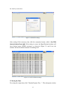
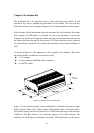
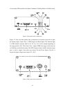
As shown in Figure 5.1, the appearance of the evaluation kit is depicted. The whole
kit should include, in addition to the main box itself,
a 12 V adapter;
an active antenna with SMA (male) connector;
two RS232 cables;
Figure 5.1 Main box of the evaluation kit.
Figure 5.2 shows the front panel of the evaluation kit. It includes (from left to right)
Power Switch, Comm. Port 2, Boot button, LED function lights, and Reset button.
The default output protocol for Comm. Port 2 is UBX binary messages with baud rate
57600 bps. The Boot button is for read/write purpose to the flash memory. The
definitions for LED lights are indicated in the figure. The Reset button can be used to