


4
List of Figures
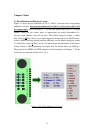
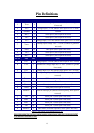
Figure 2.1 FV-25 Pin definitions (Top View)…………………………………..
Figure 2.2 A reference layout for FV-25………………………………………..
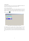
Figure 2.3 Setting of comm. port number and the value of baud rate…………..
Figure 2.4 Setting of comm. port number……………………………………….
Figure 2.5 Setting of the value of baud rate……………………………………..
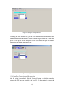
Figure 2.6 Window after correct setting…………………………………………
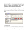
Figure 2.7 Constellation Map of GPS satellites…………………………………
Figure 2.8 Window for showing NMEA messages………………………………
Figure 2.9 “Show all MS” window………………………………………………
Figure 2.10 Available NMEA messages………………………………………………….
Figure 2.11 GPS satellite information……………………………………………
Figure 2.12 Receiver Information………………………………………………..
Figure 2.13 Tracking View……………………………………………………….
Figure 2.14 Initial position……………………………………………………….
Figure 2.15 Initial UTC time and day……………………………………………
Figure 2.16 Local time zone……………………………………………………...
Figure 2.17 Restart……………………………………………………………….
Figure 2.18 DGPS………………………………………………………………..
Figure 2.19 Setting of coordinate datum…………………………………………
Figure 3.1 HyperTerminal application……………………………………………
Figure 3.2 Connection settings……………………………………………………
Figure 3.3. Correct connection settings……………………………………………
Figure 5.1 Main box of the evaluation kit…………………………………………
Figure 5.2 Front panel of the evaluation kit……………………………………….
Figure 5.3 Back panel of the evaluation kit……………………………………….
Figure 7.1 UBX protocol structure………………………………………………...